Installation
Hardware Installation and Maintenance Manual 3
–21
Tochangethe4‐20mAboa41
1. rd from source to sink
1. Disconnect power to the analyzer.
2. Open the analyzer enclosure cover according to the procedure under
“Opening and Closing the Analyzer Enclosure Cover” on page
3-3 to gain access to the electronics panel.
3. Locate the 4-20 mA current loop board in the upper middle of the
electronics panel, as shown in Figure 1–9 on page 1–13.
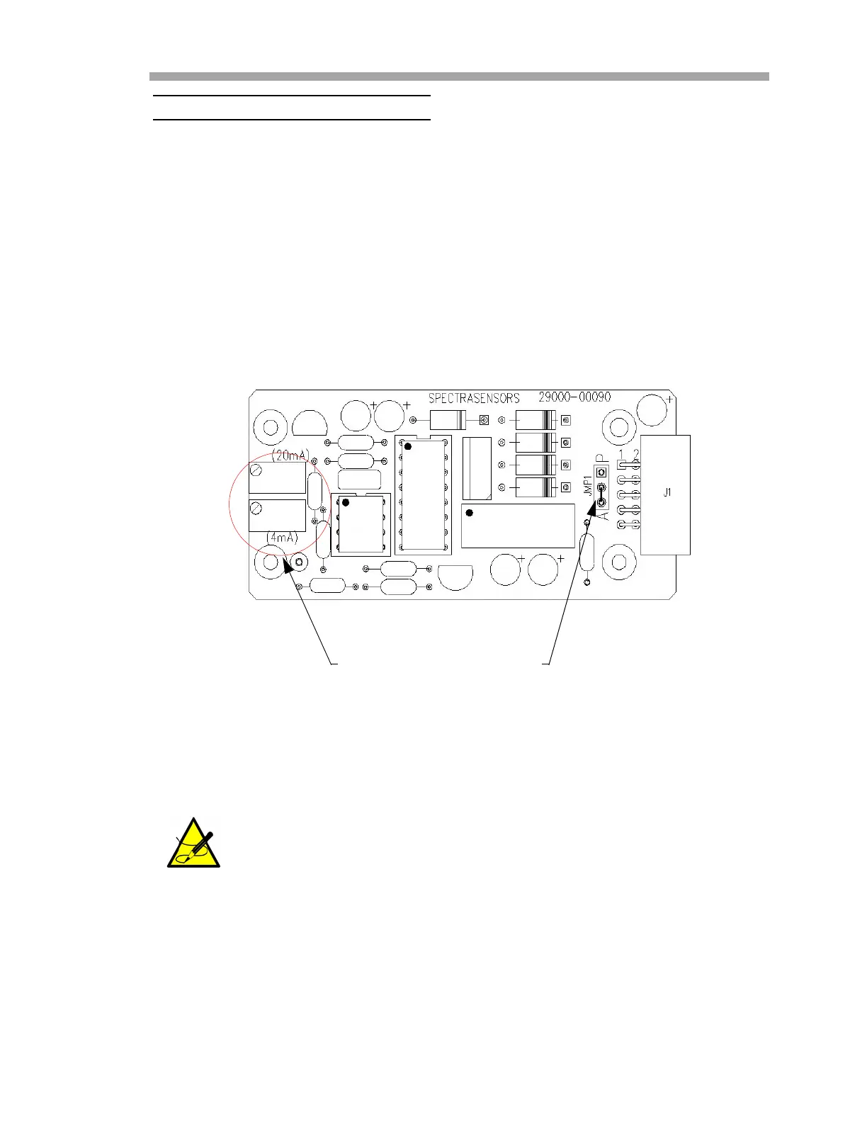
4. Remove the jumper (JMP1), shown in Figure 3–9 below, and connect
the center pin to point “A.”.
5. For 4-20 mA sink, carefully replace the jumper to connect the center
hole with point “P.”
6. Reconnect power to the analyzer. Confirm the 4 mA (minimum) and
20 mA (maximum) points (refer to the appropriate Firmware Manual
for “Scaling and Calibrating the Current Loop Signal”).
7. Close the analyzer enclosure cover according to the procedure under
“To close the analyzer enclosure cover” on page 3-3.
Needle nose pliers may be required to remove the jumper.
Figure 3–9 Analyzer 4-20 mA board
JMP1POTENTIOMETER

 Loading...


