Installation
Hardware Installation and Maintenance Manual 3
–17
4. Strip back the jacket and insulation of the 4-20 mA AI, 4-20 mA AO
and serial or Ethernet cables just enough to connect to the terminals
of block (X4).
5. Connect the 4-20 mA AI, 4-20 mA AO and serial or Ethernet wires
to the appropriate terminals, as indicated in Table 3–2 below.
6. Strip back the jacket and insulation of the alarm output and
validation request input cables just enough to connect to the
terminals of block (X3).
To avoid risk of a short circuit between adjacent connectors in
terminal blocks, add a single compression-type ferrule on each
wire prior to connecting to block (X4).
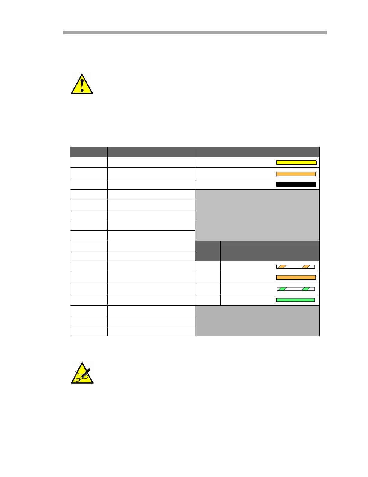
Table 3–2 Terminal block (X4) input/output signal connections
Terminal Description Service USB Converter Wire Color
1 RS-485 or TD A(–) Yellow
2 RS-485 or TD B(+) Orange
3 Serial Ground Black
4N/C
5 4-20 mA AO Ch. A (+)
6 4-20 mA AO Ch. A (–)
7 4-20 mA AO Ch. B (+)
8 4-20 mA AO Ch. B (–)
9 4-20 mA AI (+)
RJ45
Pin #
Wire Color (T568B)
Cat5(e)
10 4-20 mA AI (–)
11 Ethernet Tx+ (BI_DA+) 1 White/Orange
12 Ethernet Tx– (BI_DA–) 2 Orange
13 Ethernet Rx+ (BI_DB+) 3 White/Green
14 Ethernet Rx– (BI_DB–) 6 Green
G Serial Shield Ground
G 4-20 mA Ch. A Shield GND
G 4-20 mA Ch. B Shield GND
NOTE: The description “N/C” means no connection.
Ignore markings on the DB9 cable and follow the color code
referenced in Table 3–2 only.

 Loading...


