Expression 10000XL Revision A
DISASSEMBLY/ASSEMBLY Disassembly Procedure 40
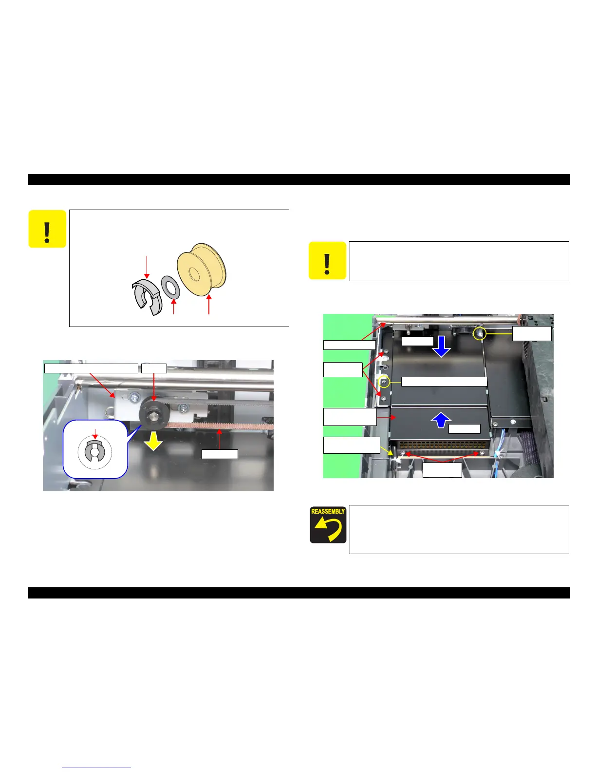
5. Remove the Fixing Ring and Pulley from the CR Belt Tension Unit, and remove the
CR belt.
Figure 4-10. Removal of CR Belt
6. Remove the seven screws (CB SCREW M3x8:2 pcs, CBP, M4x10:4 pcs,CP(S-P1),
M3x6:1 pc) that are securing Power Supply Board Cover.(
Refer to Figure 4-8
,
Figure
4-11
)
7. After lifting the front end of the Power Supply Board Cover, pull and remove it toward
you.
Figure 4-11. Removal of Power Supply Board Cover
C A U T I O N
When doing the following procedure, be careful not to lose the Ring
that is located between the Fixing Ring and Pulley.
Fixing Ring
Ring Pulley
CR Belt Tension Unit
Fixing Ring
Pulley
CR Belt
C A U T I O N
When doing the following procedure, be fully careful not to damage
the Carriage Shaft B.
Be careful not to put the Power Switch Connector Cable
between any parts.
When reinstalling the Power Supply Board Cover, match the
Power Supply Board Cover hole and boss indicated in Figure
4-11.
M4x10
(70±10Ncm)
M4x10
(70±10Ncm)
Positioning Holes and Boss
Power Supply
Board Cover
M3x6
(50±10Ncm)
Carriage Shaft B
Step 7-1
Step 7-2
Step 7-1
Power Switch
Connector Cable
 Loading...