LX-3(IO Service Manual
Product Description
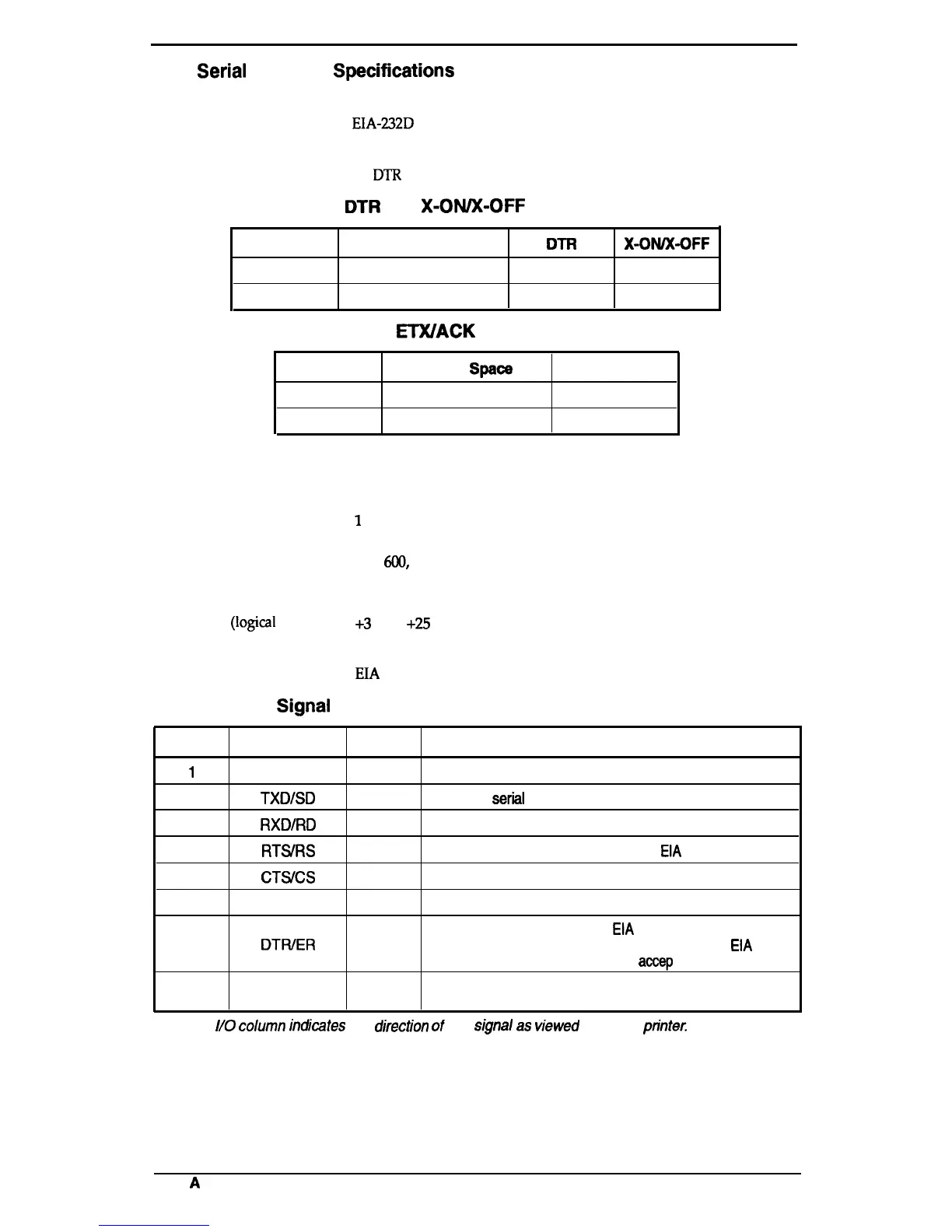
1.3.2 Serial Interface Specifkations
The LX-300 is equipped with an 8-bit serial interface, standard.
Data format:
EIA-232D
serial
Synchronization:
Asynchronous
Handshaking:
By
DTR
signal and X-ON/X-OFF protocol
DTR
and X-OIVX-OFF Protocol
State
Buffer Space
DTR
X-OWX-OFF
Busy
Less than 256 bytes
off
X-OFF
Ready
More than 512 bytes
On
X-ON
ETX/ACK Protocol
State
Buffer
Spaoe
Response Code
Busy
Less than 256 bytes
NAK
Ready
256 bytes or more
ACK
Word length
Start bits:
1 bit
Data bits:
7 or 8 bit (selectable)
Parity bit:
O or 1 bit (selectable)
Stop bits:
1
bit (transmitting)
1 bit or more (receiving)
Bit rate:
300,
6(X),
1200,2400,4800,9600, 19200 bps (selectable)
Logic level
MARK (logical 1):
–3 V to –25 V
SPACE
(logical
O):
+3
v to
+-25
v
Parity check: Odd, even, or no parity bit (selectable)
Connector:
EIA
standard 25-pin D-SUB female comector
Table 1-16. Signal and Connector Pin Assignments for Serial Interface
Pin No.
Signal Name
110*
Description
1
FG
—
Chassis ground.
2
TXDJSD
out
Transmit
seriil
data.
3
RXDIRD
In
Receive serial data.
4
RTS/RS
out
This signal is
always at the positive
EIA
level.
5
CTSVCS
In
Ignored.
7
SG
—
Return path for data and control signals.
This signal is at the positive
EIA
level when the printer is
11,20
DTWER
out
ready to accept data entry and at the negative
EIA
level
when the printer is not ready to
accep
t data entry.
6,8-10,12-
19,21-25
NC
—
No connection (not used).
●
The
//0
column
irxbtes
the
djrectkm
d
the
sjgnal
as
vjewed
from the
printec
Rev.
A
1-13

 Loading...