LX-3(IO
Sarvice
Manual
Ptvduct
Daactiption
1.5 MAIN COMPONENTS
The
main components of the LX-300 is designed for easy removal and repair. The main
components are;
■
C130
MAIN BOARD: Control board
■
C130
PSB/PSE
(120V
/
220-240V)
BOARD: Power supply board
■
M-3G1O: Printer mechanism
9
Housing
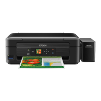
1.5.1
C130
MAIN Board
The
C130
MAINboard consists
etc.
PROM
(Program
1
CG)
\
2SC5060
/
>
(PF MOTOR Driver)
000
(Printhead Driver)
I
y
/’
00
00
000
n—
000
%
of an
E01A09
(CPU), a
Program/CG
ROM, a RAM, an EEPROM,
E01A09
(CPU)
-
2SC5~
SLA7022M
UPC78M05AHF
(CR MOTOR
(Regulator
IC)
DRIVER)
SUB
PCB
(COLOR OPTION)
Figure 1-9. C130 MAIN Board Component Layout
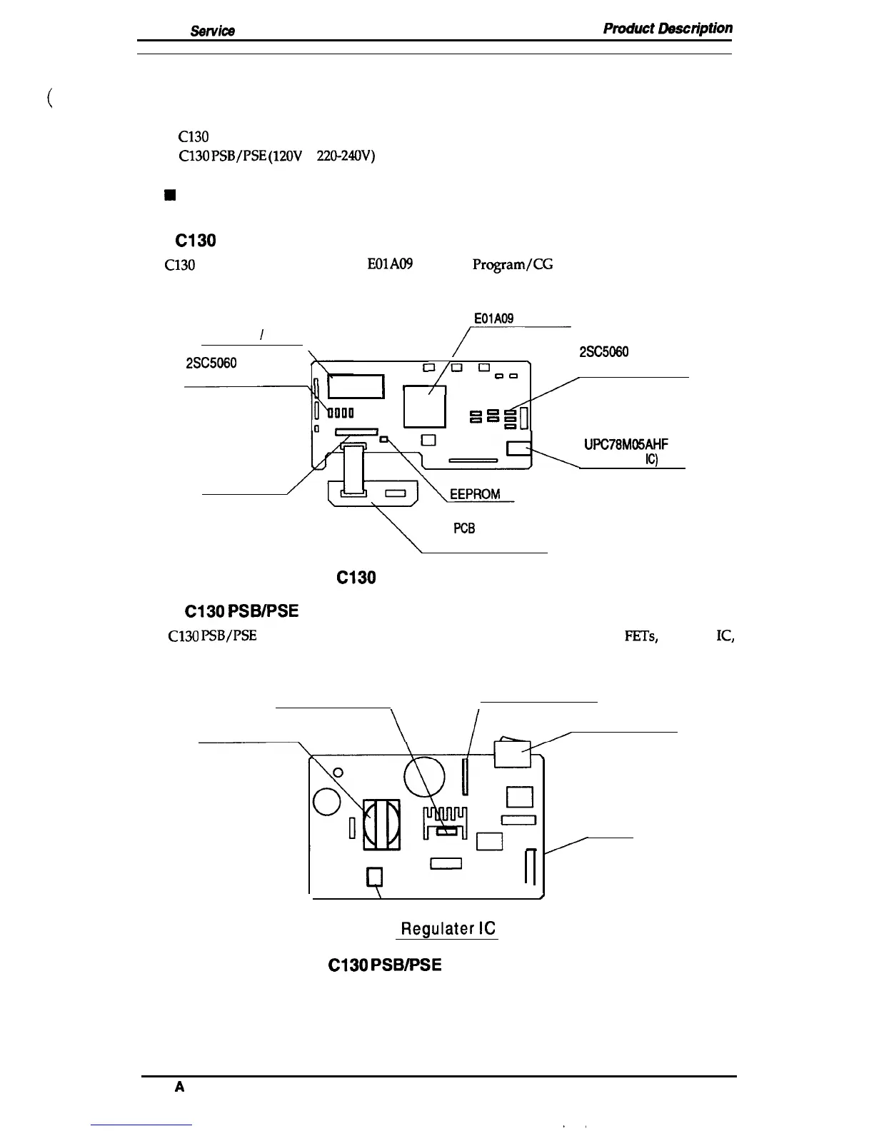
1.5.2
C130 PSB/PSE Board
The
C130
PSB/PSE
power supply board consists of a transformer, switching
FETs,
regulate
IC,
diode bridge, etc. This board has two ratings for input AC voltages.
Switching FET
Diodde Bridge
Transformer
Power Switch
Fuse
/
0
0
❑
“
o
)
\
Regulater
IC
Figure 1-10. C130 PSB/PSE Board Component Layout
Rev.
A
1-21

 Loading...