Disassembly and Assembly
LX-3tM
Service
Mhnual
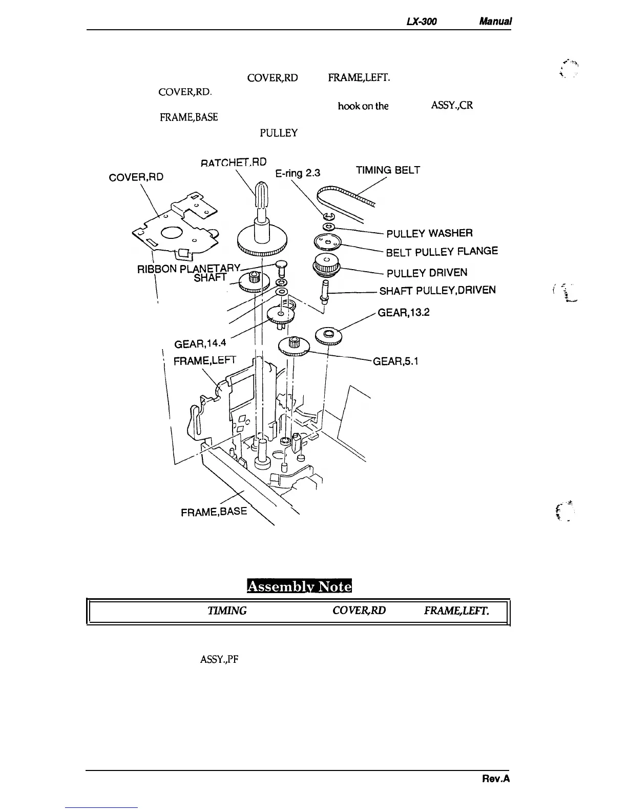
3.2.4.8 Removing the Ribbon Drive Gear Assembly
1.
Remove the printer mechanism (see Section 3.2.4).
2. Release the3 hooks attaching the
COVER,RD
to the
FRAME,LEFI’.
3. Remove the
COVER,RD.
4.
Remove the BELT TENSION SPRING between
the
hook
on
tie
MOTOR
ASSY.,CR
and the
hook
on
the
FRAME,BASE
(see Section 3.2.4.2).
5. Remove the TIMING BELT from the
PLJLLEY
DRIVEN.
RATCHET,RD
cov&&~g;,:,H,,ANGE
$-
R18BON
P~N=AR’f
1,
GEAR
SHAH
GEAR,5.1 ,16.2
‘?
ji.wLs~~~~~~~E~R’”’”
PLANE WASHER
0;
6
GEAR,13.2
SPRING WAStiER
\
GEAR,14.4
, ,
kQ
\
FRAME,BA=
\
\
A!.,+,
,,
i
,.
,
-.
,.
i
$-
,16.2
Figure 3-17. Removing the Ribbon Drive Gear Assembly
Make sure not to put the
ZZMING
BELT between the COVERJU3 and the FRAME,LEFT.
3.2.4.9
Removing the PF Gear Assembly
1.
Remove the MOTOR
ASSY.,PF
(see Section
3.2.4.1).
2.
Remove the PF gear train and the release lever.
3-16
Rev.A

 Loading...