Operating Principles
LX-3(M
Service Manual
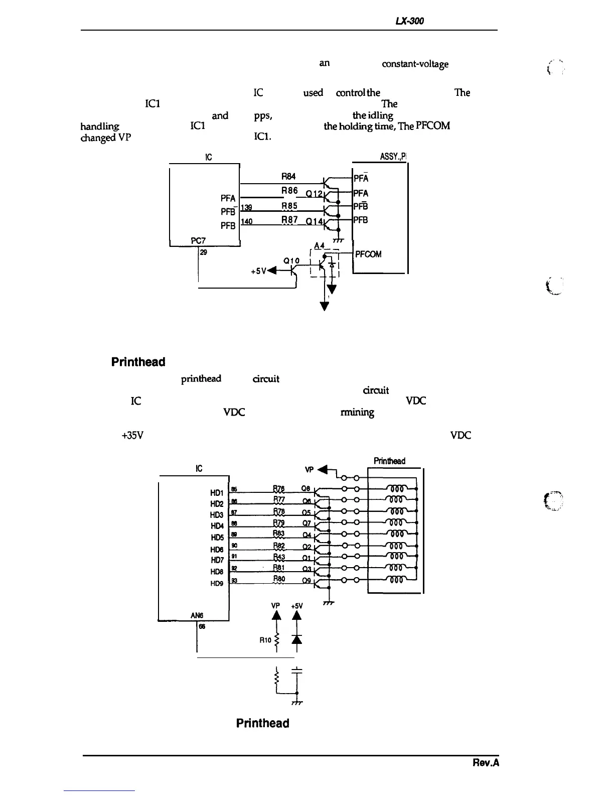
2.3.7 Paper Feed Motor Driver Circuit
Figure 2-18 shows the paper feed motor driver circuit,
an
open-100P,
constant-voltage
drive with
1-2 phase excitation.
The ports (pins 137-
140)
on the system
IC
(ICI) are
used
to
control
the
stepping motor.
The
pulse
signal
from the
IC1
controls four transistors and the stepping motor.
l%e
motor is driven at fiv
e
speeds, 800, 900, 1000, 1200,
and
1300
pps,
to correspond to
the
idling
voltage and the paper
handling
condition. The
ICI
controls motor speed. At
the
holding
time,
The
pFCOM
voltage is
chang4-VP
into VL
via A4 by the
IC1.
“
SYSTEM
IC
(ICI)
MOTOR
ASSY.,PI
(
R84
Q11
PFA
-
’
37
PF~
13s
R86
PFA
Q1
PFA
PB-
‘3
Ra5
Q13
Pm
R87
Q14
Pm
PFB
‘“O
nm7
I
‘1
*
‘L
VP
Figure 2-18. Paper Feed Motor Driver Circuit Diagram
2.3.8
Printhead Driver Circuit
Figure 2-19 shows the
printhead
driver arcuit block diagram. Print data, already expanded into
image data, is split by the CPU block and transferred to the latch
arcuit
in the gate array block in
the system
IC
(ICI). Port AN6 (pin 66) of ICI samples the voltage of the +35
VDC
line via the A/D
converter. By sampling the +35
VDC
line voltage and dete
rmining
the length of the head drive
signal, it is possible to maintain the energy supplied to the head at a constant level. If the voltage
from the
+35V
line is HIGH, ICI shortens the output pulse. If the voltage from the +35
VDC
line is
LOW, ICI lengthens the output pulse.
Printhead
SYSTEM
IC
(ICI)
I
1
‘~
HD1
HD2
HD3
HD4
HDs
HD6
HD7
HDs
HD9
F14
;p~~
At&
68
RIO
D1
~
-c?
Rll
Figure 2-19. Printhead Driver Circuit Diagram
(
{“
‘:
(
<<-:
2-16
Rev.A

 Loading...