Operating Principles
LX-WI
Service
Mimual
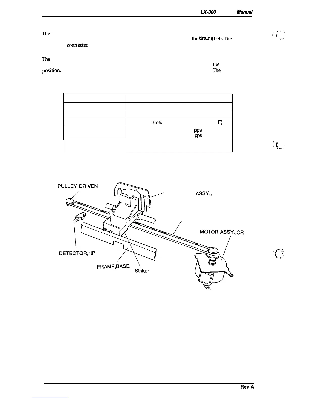
2.1.2 Carriage Movement Mechanism
The
carriage
movement mechanism consists
of the carriage assembly, CR motor assembly, timing
belt, driven pulley, HP sensor, etc.
The CR motor assembly drives
tie
tifig
belt.
me
carriage
assembly is
comected
to the timing belt, which is moved by the CR motor assembly. Figure 2-2
shows the carriage movement mechanism.
The
printer detects the carriage home position with the HP sensor. This sensor is the basis for
determining the carriage home position.
The HP sensor informs the CPU of
the
carnage home
position.
The sensor is ON, when the carriage is pushed to the right or left.
The
striker on the
carriage actives the sensor to indicate the carriage home position, which toggles the sensor to OFF.
Table 2-1. CR Motor Assembly Specifications
Category
Requirement
Type
4-phase, 48-pole, PM-type stepping motor
Drive Voltage
31.5 -38.5 VDC
Coil Resistance
180 ohms
*
7Y0
(per phase, at 25° C, 77°
F)
Drive Pulse Frequency
Normal Mode Draft
1320
p~
Color Mode Draft
1980
PPS
Excitation Method
Constant-voltage 2-2 phase excitation
1-2 phase excitation
CARRIAGE
ASSY.,
TIMING BELT
.,
Figure 2-2. Carriage Movement Mechanism
,CR
2-2
Rev.A

 Loading...