Disassembly and Assembly
LX&Xl
Service M%ual
3.2.3.1
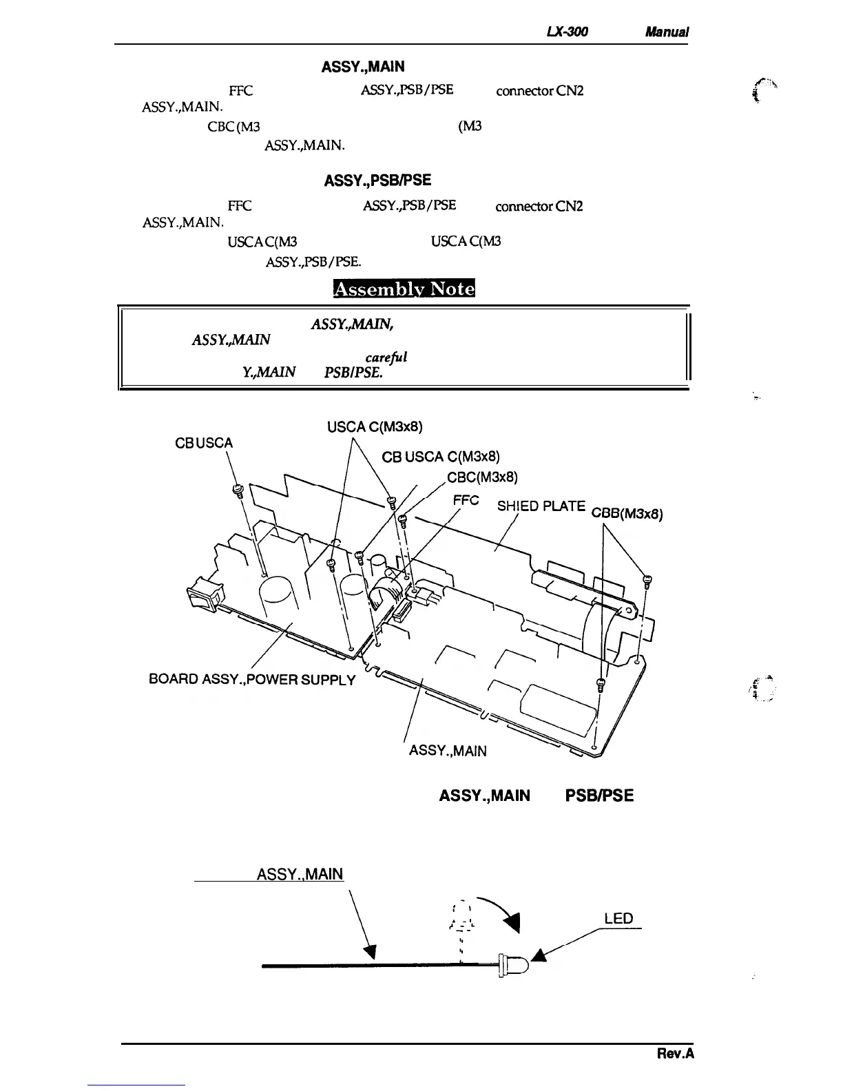
Removing the BOARD
ASSY.,MAIN
1.
Remove the
FFC
of the BOARD
ASSY.,PSB/I’SE
from
comector
CN2
of the BOARD
fl::y
ASSY.,MAIN.
%.
.
.
2. Remove the
CBC
(M3
x8) screw and the3 CB USCAC
(M3
x 8)
3. Remove the BOARD
ASSY.,MAIN.
3.2.3.2 Removing the BOARD
ASSY.,PSBIPSE
1.
Remove the
FFC
for the BOARD
ASSY.,PSB/I’SE
from
comector
CN2
on the BOARD
ASSY.,MAIN.
2. Remove the CB
USCA
C(M3
x
10) screw and 2 CB
USCA
C(M3
x 8) ssrews.
3. Remove the BOARD
ASSY.,PSB/PSE.
●
When replacing the BOARD
ASSY.,MA.IM
bend the LED lead wires parallel to the
BOARD
ASSY.J4AIN
(see Figure 3-7).
. The SHIELD PLATE is easily bent; be
carefil
when tightening the screws that attach it to
the BOARD ASS
Y.,MAIN
and
PSBIPSE.
CB
USCA
C(M3X8)
CB
USCA
C(M3X1O)
L
A
k
CB
USCA
C(M3X8)
/
,CBC(M3X8)
tiOO\MdXU)
‘=.
----
BOARD
ASSY.,MAIN
‘v
Figure 3-6. Removing the BOARD ASSY.,MAIN and PSB/PSE
BOARD ASSY.,MAIN
\
Figure 3-7. Bending the LED Lead Wires
3-8
Rev.A

 Loading...