LX-300
Sarvice
Manual
Oparating
Principk
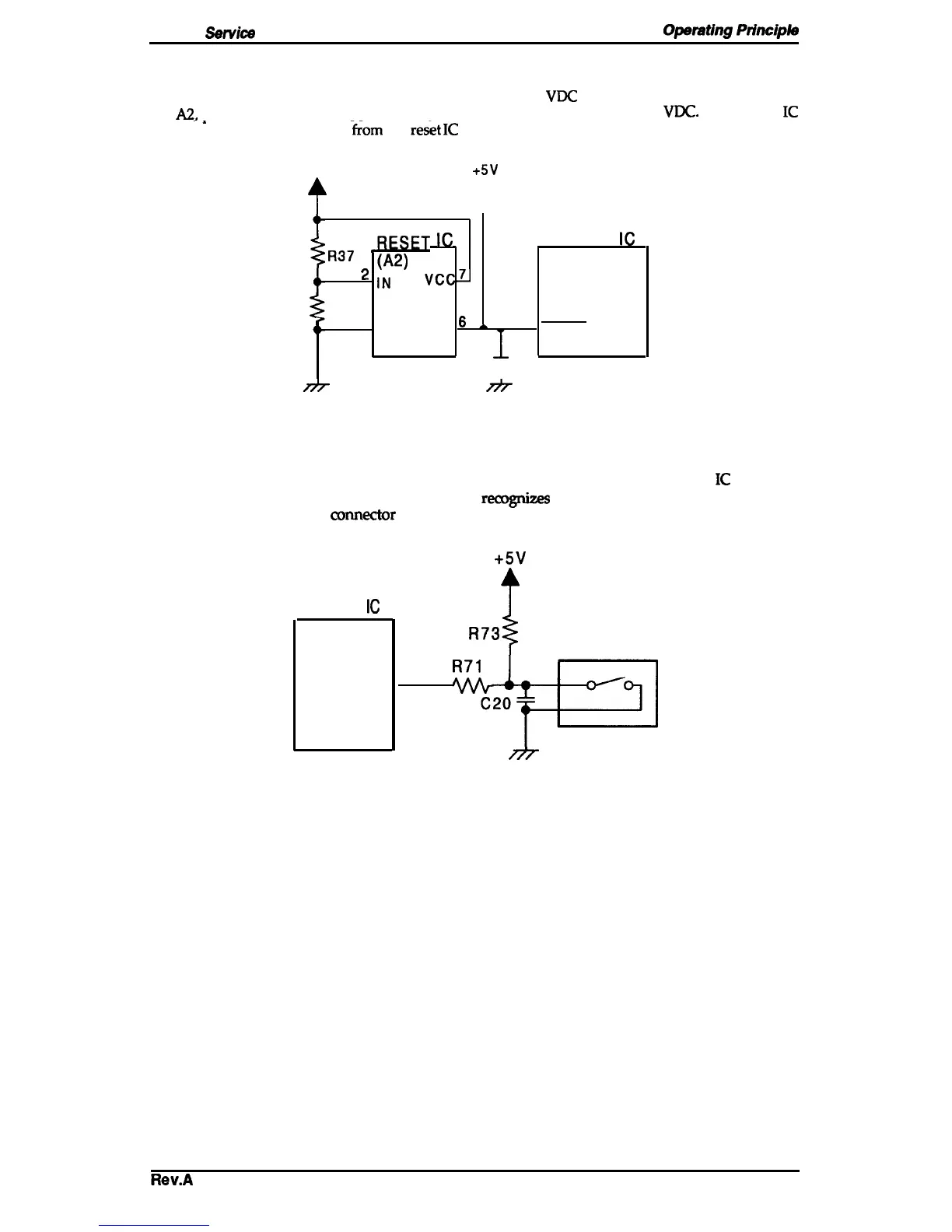
2.3.2 Power On Reset Circuit
When
the power supply is turned on, the VL goes up to +9
VDC
immediately, but reset IC output
(IC
A2,
Pin 6) is delayed for approximately 80-
1 ma before going up to +9
VDC.
The system
IC
-.
receives this
Low
level
signal
‘~om
the
res&
IC
and resets itself.
VL
+5V
?
t
3ESFT
IC
SYSTEM
IC
R37
*
\:2)
(ICI)
v(-.~
~
R38
4
4
GND OUT
6
&
‘
3
RESET
T
C24
Figure 2-13. Power On Reset Circuit Diagram
2.3.3 Home Position Sensor Circuit
This printer has a connector switch to sense the carriage home position. The system
IC
receives a
signal (HIGH or LOW) from the HP sensor and
remgnize
the carriage home position when the
printer is turned on. The comector switch is closed (LOW) when the carriage is in the home
position and is open (HIGH) when the carnage is out of home position.
SYSTEM
IC
(ICI)
SCK
Figure 2-14. Home
+5V
R73
I
HP Sensor
34
R71
Position Sensor Circuit Diagram
Rev.A
2-13

 Loading...