LX300
Service Manual
Disassembly and Assembly
3.2.4.7
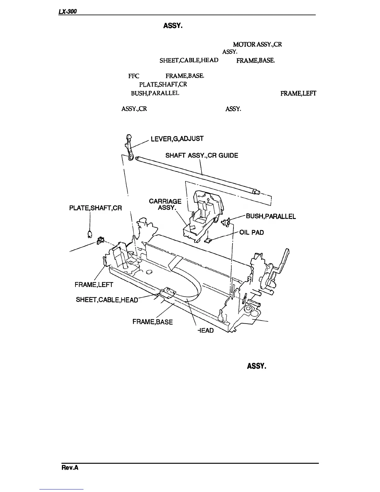
Removing the CARRIAGE
ASSY.
1.
Remove the printer mechanism (see Section 3.2.4).
2.
Remove
the
BELT TENSION SPRING from the hook
on the
MOTOR
ASSY.,CR
(see Section
3.2.4.2), and remove the TIMING BELT of the CARRIAGE
ASSY.
from the PULLEY DRIVE.
3. Release the hook that attaches the
SHEET,CABLE,HEAD
to the
FRAME,BASE.
Slide the cable
to the left and remove it.
4. Remove the printhead
FFC
from the
FRAME,BASE.
5. Remove the GROUNDING
PLATESH~,CR
from the left side of the printer mechanism.
6. Rotate both sides of the
BUSH,PARALLEL
ADJUST and remove them from the
FRAME,LEFT
and RIGHT.
7. Remove the SHAFT
ASSY.,CR
GUIDE and the CARRIAGE
ASSY.
$(=
LEVER,G,ADJUST
p
\,
GROUNDING
PLATE,SHAH,CR
\
RALLEL
ADJUST
BUSH, PARALLEL
ADJUST
SHE~,CABLE,HEAD
FRAME,BASE
\’-Ql
~
FRAME, RIGHT
CABLE HEAD
Figure 3-16. Removing the CARRIAGE
ASSY.
Rev.A
3-15

 Loading...