Operating Principles
LX#Xl
Service Manual
2.3.10
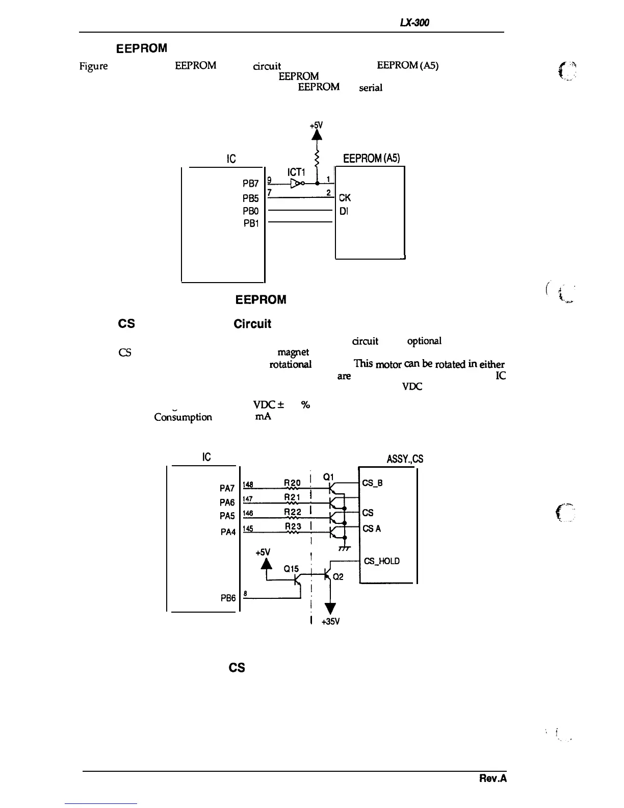
EEPROM
Control Circuit
Figure 2-22 shows the
EEPROM
control arcuit block diagram. ‘The
EEPROM
(A5)
contains such
information as the top-of-form position.
The
EEPROM
is non-volatile memory, so information is
not lost if the printer is powered off.
Since the
EEPROM
is a
serial
I/O-type device, the CPU
converts 8-bit data into serial data.
+5V
4
SYSTEM
IC
(ICI)
PB7
PB5
PBO
PB1
-+-h
ICT1
9
1
7
2
2
3
3
4
EEPROM
(A5)
Cs
CK
DI
Do
J
Figure 2-22. EEPROM Control Circuit Diagram
2.3.11
CS
Motor Assembly
Circuit
Figure 2-23 shows a block diagram of the CS motor assembly
arcuit
in the
optioml
color upgrade
kit. The
CS
motor assembly is a pe
rmanent
ma~et
(PM) stepping motor, driven with
2-2
phase
excitation in proportion to the desired
mtatioti
speed.
W
motor
GUI
be
rotated
in
either
direction and stopped at any position. Four phase signals
are
directly output from the system
IC
and pass through a transistor array. The drive voltage is constant (i.e., +35
VDC
from the VP line).
Source Voltage
35 VDc
*
10
Yo
Current
Con~ump60n
245
mA
( peak)
SYSTEM
IC
(ICI)
PA7
PA6
PA5
PA4
PB6
MOTOR
ASSY.,CS
F
a
R20
Q1
14s
CS-B
147
R21
I
CS_A
14a
R22
I
CS B
14s
R23
I
(XA
+5V
*I
t
I
Printer
N
I
+35V
“-%
(:
,...m
f,,;.
Color Upgrade Kit
Figure 2-23.
CS
Motor Assembly Circuit Diagram
2-18
Rev.A

 Loading...