LX300
Sarvica
Manual
Operating
Principk
2.2.2 Power Supply Circuit Operation
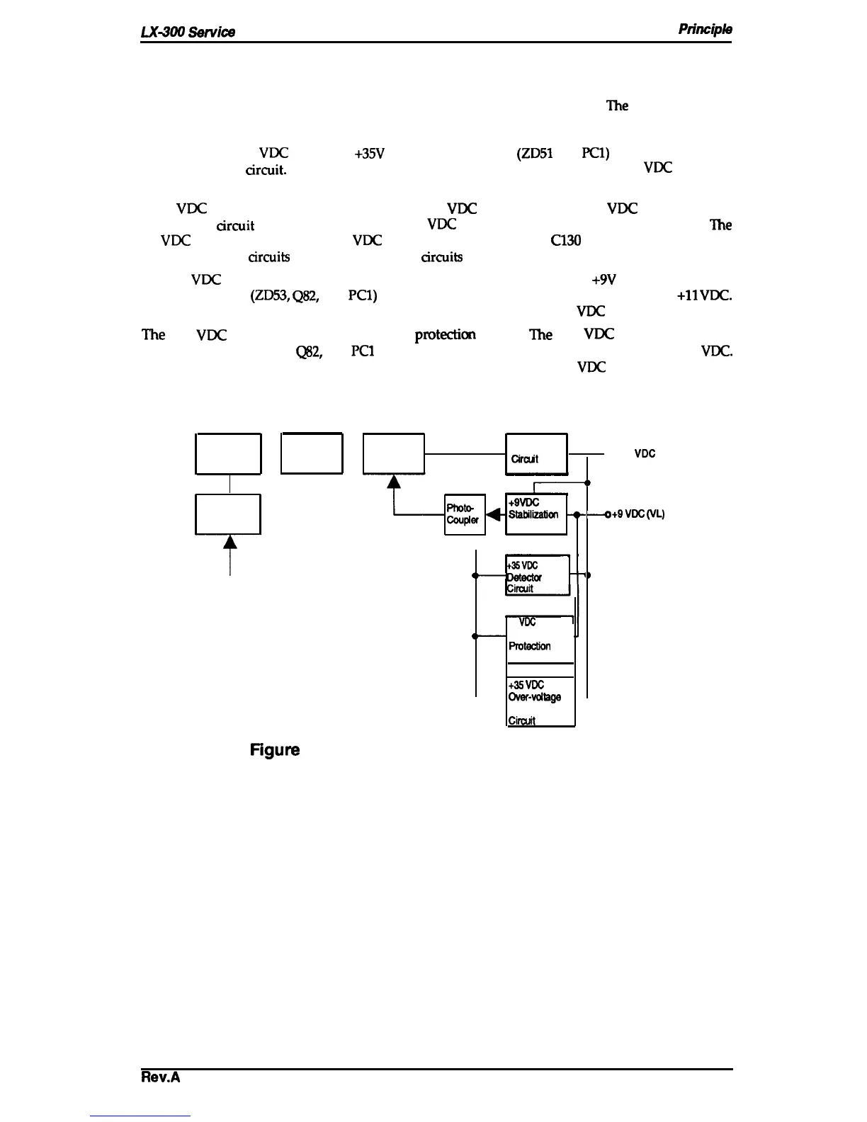
Figure 2-11 shows a block diagram of the power supply circuitry. When AC power is supplied to
the printer from an external power source, a filter circuit removes the noise.
l%e
AC voltage then
undergoes full-wave rectification and is smoothed to produce the direct current supply voltage.
This voltage is fed through a switching circuit and secondary smoothing circuit to produce the
stepped down +35
VDC
supply. A
+35V
line voltage detector
(ZD51
and PCl) circuit is connected
to the switching
arcuit.
This feedback control arrangement ensures that the +35
VDC
supply is
kept stabilized.
A +9
VDC
supply is created by putting the +35
VDC
line through the +9
VDC
power supply
circuit. This arcuit further steps down the +35
VDC
voltage and outputs a stabilized supply.
The
+9
VDC
output is stabilized to +5
VDC
using the regulator on the
C130
MAIN board assembly.
There are several arcuits to protect the supply arcuits and avoid danger.
The +9
VDC
line contains a voltage overload protection circuit. The
+9V
voltage overload
protection circuit
(ZD53,
Q82,
and
PC1)
cuts the supply if the voltage reaches or exceeds
+11
VDC.
It stops switching circuit operation, which stops the output from the +35
VDC
line.
‘he
+35
VDC
line has a voltage overload
protectkm
circuit.
l’he
+35
VDC
voltage overload
protection circuit ( ZD52,
Q82,
and
PC1
) cuts the supply if the voltage reaches or exceeds +36
VDC.
It stops switching circuit operation, which stops the output from the +35
VDC
line.
Full-Wave
Rectification —
Smoothing
Switching
Smoothing
Circuit
Circuit
Circuit
CirciM
o +35 VDC (VP)
D
Pflot&
+9VDC
Filter Circuit
Couplef
+
Sfabilizatial
+
+
+9VDC
(VL)
circuit
A
+3SVDC
line
(
—
~
)
AC Line
+9
VDC
line
d
—
over-voltage
FMecthn
Circuit
+35
VDC
line
—
OWr-volfaga
Protection
Cinxit
figure
2-11. Power Supply Circuit Block Diagram
Rev.A
2-11

 Loading...