EPSON Stylus COLOR 670 Revision A
Appendix Connector Summary 130
7.1 Connector Summary
7.1.1 Major Component Unit
Major component unit of this printer is as follows.
o MAIN Board (C301MAIN)
o Power Supply Board (C301PSB/PSE)
o Control Panel (C209PNL)
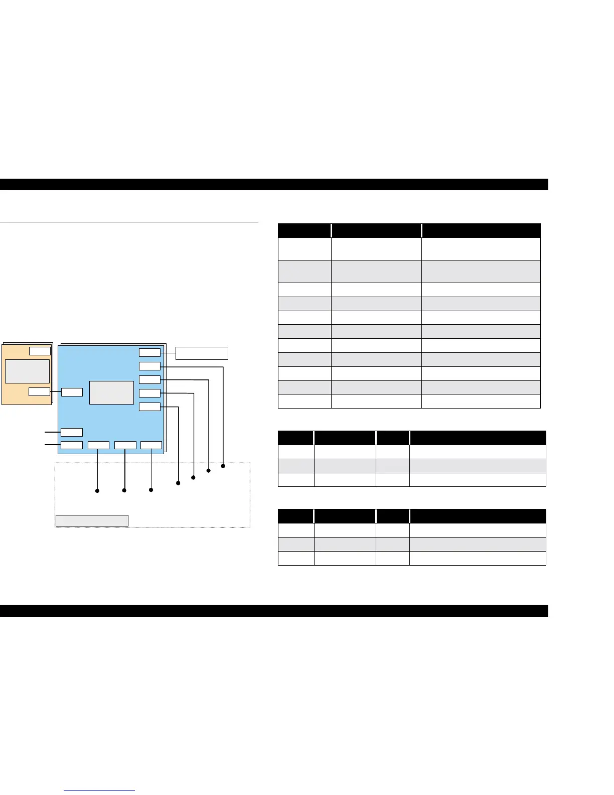
The figure below shows how these components are connected.
Figure 7-1. Connection of the Major Components
CN11
Control Panel
CN4
CN5
CN6
CN12
CN9CN8CN7
CN2
CN1
CN10
CN2
CN1
Parallel I/F
USB I/F
HP Senso
PE Sensor
ASF HP Sensor
CR Motor
Printhead
Printhead
PF Motor
C301 MAIN
Board
C301 PS
Board
Printer Mechanism
Table 7-1. Connector Summary for C259Main
Connector Function Table to refer.
CN1
Parallel Interface
Connector
Refer to “IEEE-1284 Parallel I/F
(Forward Channel)” on page 18
CN3 USB Interface Connector
Refer to “USB (Universal Serious
Bus)” on page 22
CN4 HP Sensor Table 7-2
CN5 PE Sensor Table 7-3
CN6 ASF Sensor Table 7-4
CN7 PF Motor Table 7-5
CN8 Printhead Table 7-6
CN9 Printhead Table 7-7
CN10 Power Supply Connector Table 7-8
CN11 Control Panel Table 7-9
CN12 CR Motor Table 7-10
Table 7-2. Connector CN4
Pin Signal Name I/O Function
1 HP In Sensor detect signal
2 GND --- Ground
3 HPV --- Sensor Power Supply
Table 7-3. Connector CN5
Pin Signal Name I/O Function
1 PE In Sensor detect signal
2 GND --- Ground
3 PEV --- Sensor power supply
 Loading...


