EPSON Stylus COLOR 670 Revision A
Disassembly and Assembly Disassembly 95
4.2.5.9 PE Sensor Assembly Removal
1. Remove the Housing. (See “Housing Removal” on page 72)
2. Remove the ASF Assembly. (See “ASF Assembly Removal” on page 85)
3. Release 2 PE Sensor Assembly Securing Hooks from the Top Frame
Cutoffs and remove PE Sensor Assembly by sliding it upward.
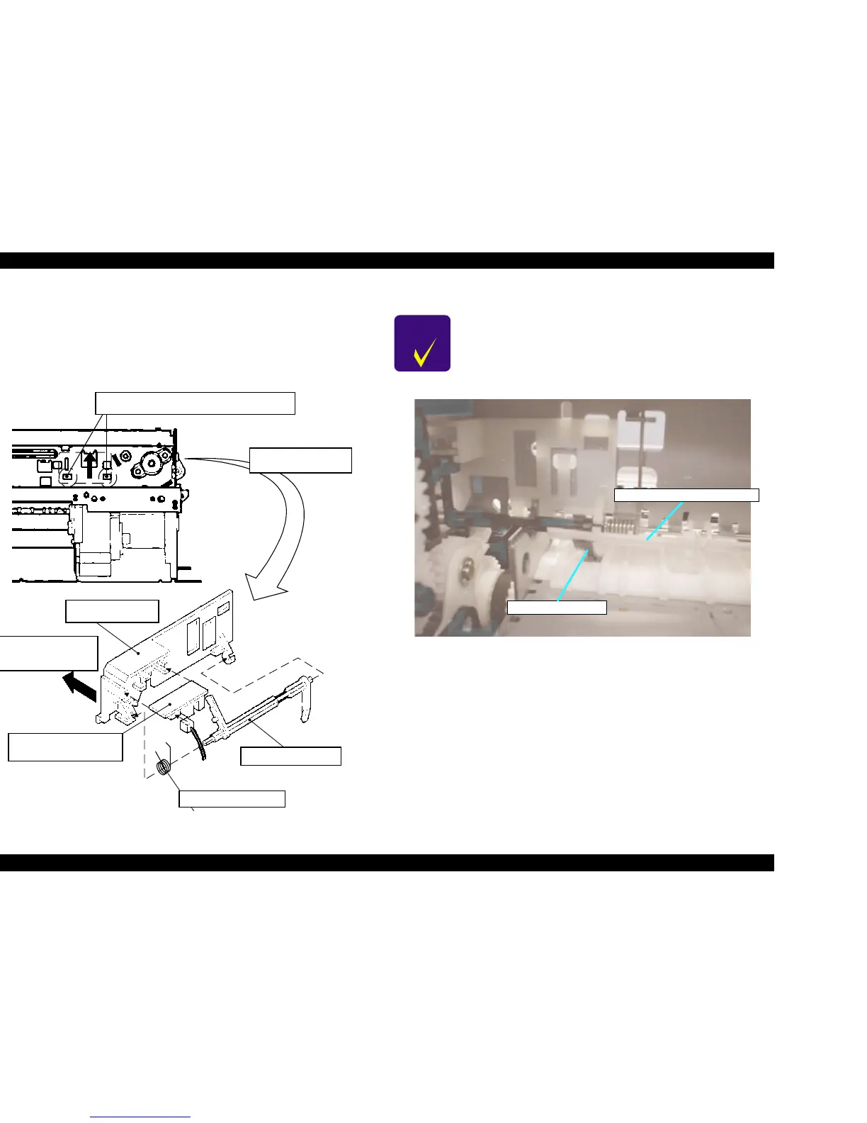
Figure 4-43. PE Sensor Assembly Removal
Figure 4-44. PE Sensor Lever Head Setting Position
After releasing two hooks, remove the PF
Sensor Assembly, sliding it upward.
(From back side of
the frame)
PE Sensor Holder
This side should
be installed on the
frame.
PE Sensor Board
Assembly
Torsion Spring 0.22
PE Sensor Lever
CHECK
POINT
When installing the PE Sensor Assembly, make sure that the
sensor lever is correctly inserted into the hole of Paper Guide
Assembly.
PE Sensor Lever Head
Right Paper Guide Top Assembly
 Loading...


