EPSON Stylus COLOR 670 Revision A
Operating Principles Electrical Circuit Operating Principles 51
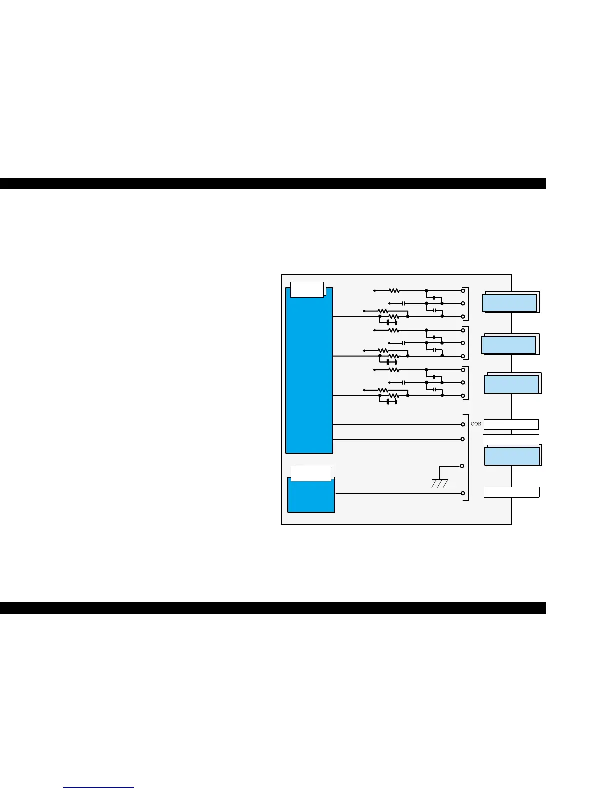
2.2.2.7 Sensor Circuit
C301MAIN is equipped with the following five sensors to detect the status of
the printer.
o HP Sensor
HP sensor uses photo interrupter method. HP sensor detects the
carriage HP (home position). HP is the standard position for the print
start position. When CR unit is within the home position, the sensor
outputs +5V: When CR unit is out of the home position, the sensor
outputs 0V.
o PE sensor
PE sensor uses photo interrupter method. PE sensor detects paper on
paper path of the printer. If paper passes, PE sensor outputs 0V. If
there is no paper, the sensor outputs +5V. The signal output from this
sensor and the stepping pulse of PF motor determines the paper top
position and the bottom position and it is reflected to the printable
area of paper feed direction.
o ASF HP sensor
ASF HP sensor uses photo interrupter method. This sensor consists of
the ASF HP detector wheel, which is attached on the ASF LD roller
shaft, and a photo sensor. The ASF HP detector wheel has a small
window and when this part is positioned between photo sensor
terminals, the sensor detects ASF HP. When this window is within the
ASF HP, the sensor outputs 0V, and when it is out of ASF HP, +5V is
output. This sensor detects the ASF return lever position at the power
on and detects standby state of the ASF LD roller.
o Thermistor (TH)
The thermistor is attached directly on the printhead driver board. It
monitors the temperature around the printhead and determines the
proper head drive voltage according to the ink viscosity that varies by
the temperature. This information is fed back to the ASIC analog port.
When the temperature rises, the head drive circuit lowers the drive
voltage: When the temperature lowers, the head drive circuit rises the
drive voltage.
o Black/ Color cartridge sensor (COB/ COC)
Cartridge sensor uses mechanical method. This sensor detects
whether a black or color ink cartridge is installed in the CR unit. When
an I/C is installed, this sensor outputs 0V: When no I/C is installed, the
sensor outputs +5V.
The block diagram for the sensor circuit is shown below:
Figure 2-19. Sensor Circuit Diagram
+5V
+5V
PE
PEV
HP
GND
GND
GND
HPV
ASF
GND
ASFV
+5V
+5V
+5V
+5V
+5V
+5V
+5V
5
2
3
THM
coc
79
80
105
Black I/C sensor
Color I/C sensor
Head thermistor
IC2
E05B70**
IC1
H064F2328F
SW A2
SW A0
SW A1
SW C0
SW C1
CPU
AN0
CN9
Head FFC
CN5
PE Sensor
CN4
CR HP Sensor
CN6
ASF HP Sensor
 Loading...


