EPSON Stylus COLOR 670 Revision A
Disassembly and Assembly Disassembly 73
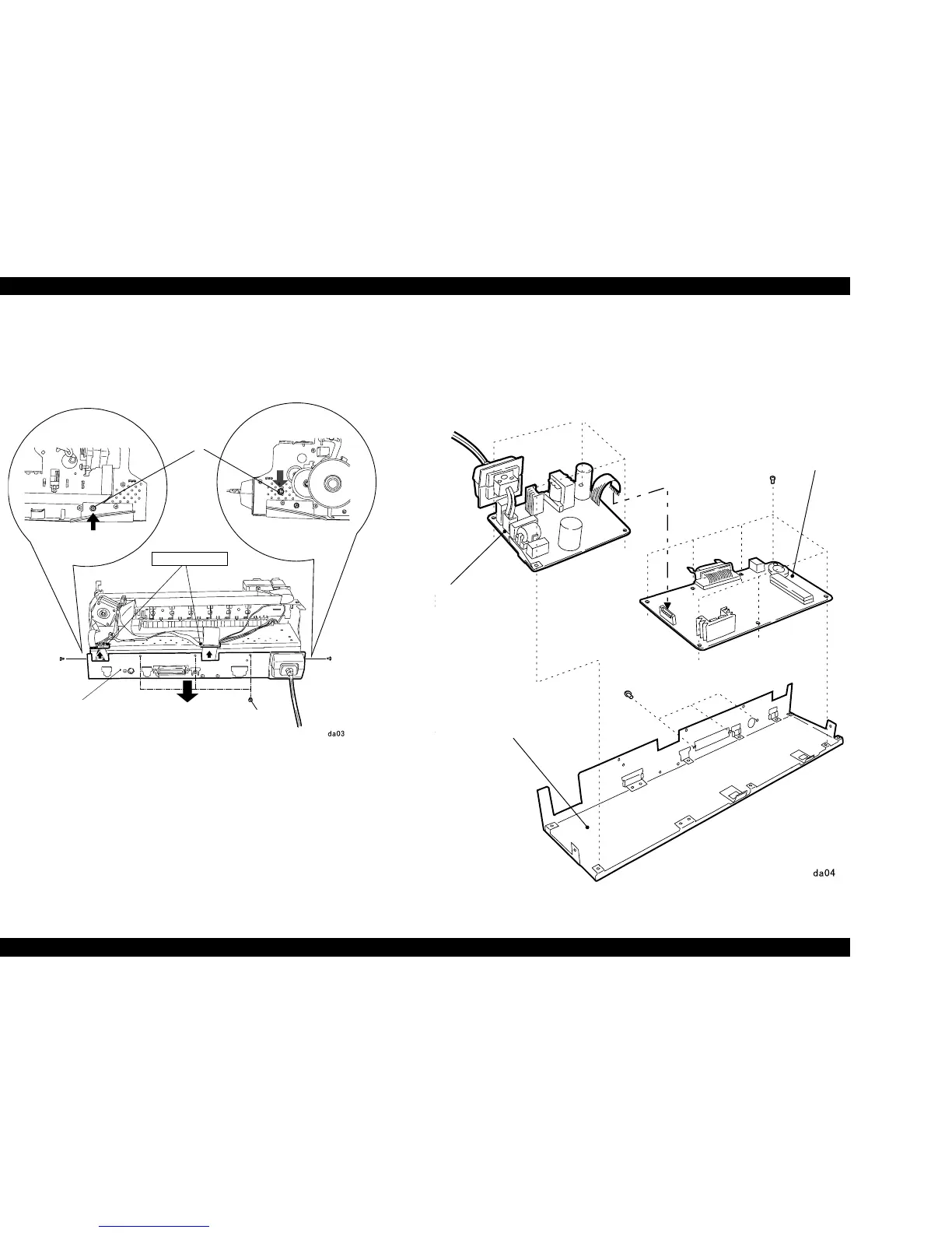
4.2.2 Circuit Board Assembly Removal
1. Remove the Housing. (“Housing Removal” on page 72)
2. Remove 5 screws securing the Printer Mechanism to the M/B Shield Plate.
Figure 4-3. M/B Shield Plate Removal
3. Slightly pull out the M/B Shield Plate and remove the cable holder
installed on the M/B Shield Plate.
4. Disconnect all the cables from the connectors on the C301MAIN Board.
5. Remove the Circuit Board Assembly from the Printer Mechanism.
6. When removing each board unit from M/B Shield Plate, remove screws
securing each board (C301MAIN Board: 10 screws, C301PSB/PSE: 4
screws) and remove the boards respectively.
NOTE: When removing each board separately, release the lock of the
connector CN10 and pull the cable out of CN10.
.
Figure 4-4. C301MAIN / C301PSB/PSE Removal
Screws
Screw
M/B Shield Plate
Cable Holders
M/B Shield Plate
Power Supply Board
(C301 PSB/PSE)
MAIN Board
(C301MAIN)
 Loading...


