EPSON Stylus COLOR 670 Revision A
Operating Principles Electrical Circuit Operating Principles 47
2.2.2.2 Printhead Driver Circuit
The printhead driver circuit consists of the following two components:
n Head common driver circuit
(Common driver IC15 & Wave amplifier transistor Q2, 3)
n Nozzle selector IC on the printhead driver board.
The common driver (IC15) generates a reference drive waveform according to
the output signals from the ASIC (IC2). The reference drive waveform is
amplified by the transistors Q2 and Q3 and then transferred to the nozzle
selector IC on the head board. Print data is converted to serial data by the
ASIC and then sent to the nozzle selector IC on the head board. Based on the
serial data, the nozzle selector IC determines the nozzles to be actuated. The
selected nozzles are driven by the drive waveforms produced by the common
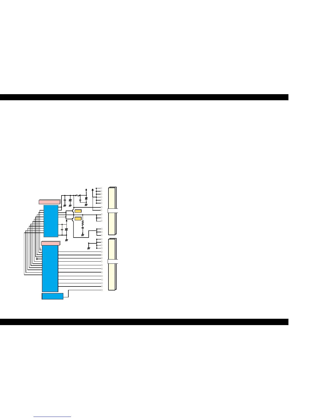
driver. See Figure 2-14 for the printhead driver circuit block diagram.
Figure 2-14. Printhead Drive Circuit
o
Printhead Driver CircuitHead common driver circuit
The reference head drive waveform is produced in the common driver
(IC15) based on the following 12 signal lines output from the ASIC
(IC2); A0-A4, CLK1, CLK2, FLOOR, RST, DATA, DCLK, and E.
Based on the DATA signal output from the ASIC (IC2), the original
data for the head drive waveform is written in the memory in the
common driver (IC15). The addresses for the written data are
determined by the A0 - A4 signals, and, of among, data used to
determine the waveform angles is selected and appropriate head
driver waveform is generated. Generated head driver waveform is
transferred to nozzle selector IC on the head driver board and applied
to the nozzle PZT specified by nozzle selector IC.
o Head nozzle selector circuit
Printing data are allocated to the six rows, the number of the head
nozzle rows, and converted into serial data by the ASIC (IC2). Then the
converted data is transferred to the nozzle selector IC through the
seven signal lines (SI0 to SI5. SI6 is not used in this product). Data
transmission from the ASIC to the nozzle selector synchronizes with
the SCK clock signal and the LAT signal. Referring to the transferred
data, nozzles to be activated are selected, and the PZTs of the selected
nozzles are driven by the drive waveform output from the head
common driver.
V C C 4 5
Vcc45_2
N P N B
F B
P N P B
VOUTGND
F1
VHC TL
22
20
COC
SCK
COB
THM
16
15
1
11
3
79
SW C0
65
AN0
105
A0
A1
A2
A3
CLK1
CLK2
/FLOOR
/R S T
DATA
DCLK
/E
HW A0
HW A1
HW A2
HW A3
HW A4
HW CLK1
HW CLK2
/H W F L R
/H W R S T
HW SDATA
HW SCLK
/H W S L A T
SI1
12
HNCHG
+42
23
18
16
13
12
11
GND2
GND2
GND2
COM
COM
COM
VHV
10
VCC 5
+5
24
14
SW C1
80
66
NCHG
3
HS01
SI2
HS02
10
SI3
HS03
8
SI4
9
HS04
SI5
HS05
7
SI6
HS06
H 064F2328F
(IC 1 )
GND
GND
GND
GND
13
6
4
56
58
59
62
63
50
51
52
53
55
54
49
28
27
26
25
3
4
5
6
29
30
1
HSOCLK
67
68
69
71
72
73
SP
5
74
HS0CM D
CN9
E05B 70**(IC 2)
C XA 2128S (IC 15)
Q2
Q3
16
15
14
GND
GND
GND
GND
GND
GND
+5V
VDD
CN8
 Loading...


