EPSON Stylus COLOR 670 Revision A
Operating Principles Electrical Circuit Operating Principles 46
2.2.2.1 Main elements
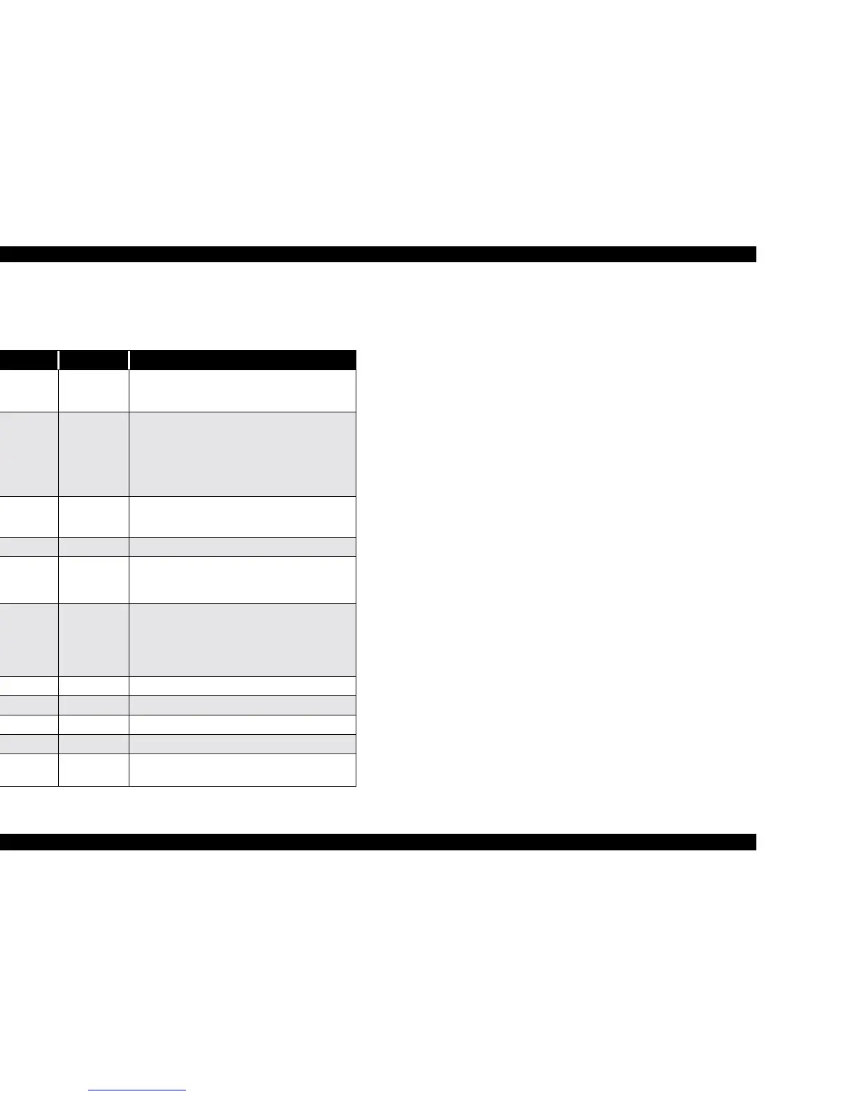
Table 2-8 shows the main elements on C301MAIN.
Table 2-8. Main Elements
IC Location Function
CPU
HD64F/2328F
IC1 (3.3V)
16bit CPU mounted on the MAIN board is driven
by clock frequency 24MHz and controls the
printer.
Gate Array
E05B70**
IC2
(3.3V & 5.0V)
• Motor Control
• Head voltage control
• EEPROM control
• Sensor supervise
• Timer IC supervise
• Parallel I/F, USB I/F control
PROM IC3 (3.3V)
• Capacity 4/8/16MB, Bus= 16 bit EEPROM
• Program or program + CG (Character
generator)
RAM IC17 (3.3V) Bus= 16 bit, 4Mbit DRAM
AT93C56 IC6 (5.0V)
2kbit EEPROM
• Default value setting
• Parameter backup
RTC-9810SA IC5 (5.0V)
Reset/ Timer IC
• For +5V; reset when +4.3V is detected
• For +42V, reset when +35.5 is detected
• Timer function is attached powered by
lithium battery.
74V161284 IC9 (5V) IEEE1284 parallel I/F transceiver IC
PDIUSBP11A IC10 (3.3V) USB Rev1 transceiver
LB11847 IC13 CR motor drive IC
LB11847 IC14 PF/ PUMP/ ASF motor drive IC
CXA2128S IC15
Head drive control HIC
• Generates head common voltage.
 Loading...


