EPSON Stylus COLOR 670 Revision A
Disassembly and Assembly Disassembly 82
4.2.5.3 CR Motor Assembly Removal
1. Remove the Housing.(See “Housing Removal” on page 72)
2. Rotate Combination Gear, 6, 34.4 toward the front of the printer and
disengage the CR Lock Lever. Then, manually move the CR Assembly to
the center of the platen.
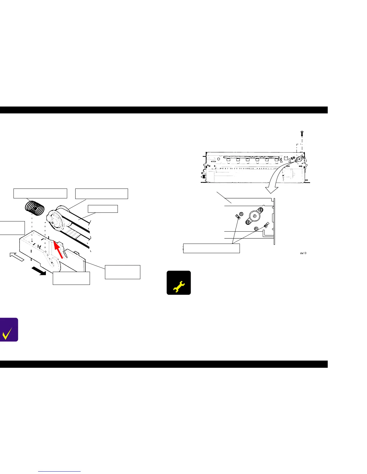
3. Push the Driven Pulley Holder toward the interior of the Left Frame and
loosen the Timing Belt. Remove the Timing Belt from the CR Motor Pinion
Gear or pull the Driven Pulley Assembly diagonally from the Driven Pulley
Holder to the top (refer to the arrow in the figure below.).
Figure 4-14. Timing Belt Removal
4. Remove 2 screws securing the CR Motor, and remove CR Motor
Assembly.
Figure 4-15. CR Motor Assembly Removal
CHECK
POINT
When installing CR Motor Assembly, be sure that 2
projections of the Motor Bracket are inserted to the position
marking holes of the frame.
Compression Spring 19.6
Driven Pulley Assembly
Timing Belt
To the Exterior
of Side Frame
To the Interior of
Side Frame
Driven Pulley
Holder
ADJUSTM ENT
REQUIRED
After replacing CR Motor Assembly, perform
the Bi-D adjustment. (See “Bi-D Adjustment” on page 112)
Top Frame
The projections of motor assembly
must locate inside the holes.
 Loading...


