EPSON Stylus COLOR 670 Revision A
Disassembly and Assembly Disassembly 81
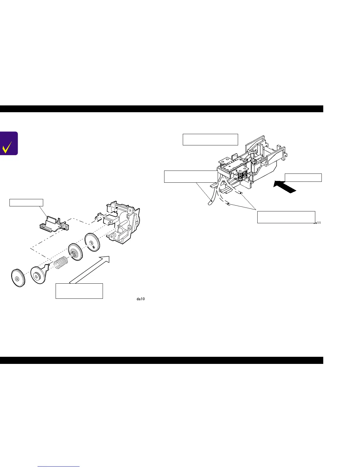
Figure 4-12. Components of Pump Assembly
Figure 4-13. Ink Tube Routing
CHECK
POINT
n Since the spring is included among the gears in the
Pump Assembly, be careful that the parts do not pop out
during disassembly and assembly. (Refer to the Figure
4-12 below.)
n When assembling, be careful not to crush nor leave any
stress on the ink tube connecting the Pump Assembly
and the Cap Assembly. (Refer to the Figure 4-13.)
After installing the Pump Assembly, rotate the
Combination Gear, 6, 34.4 and check if the Head Cleaner
moves back and forth. (Perform this check while holding
the Cap Assembly to the right of the frame.)
Head Cleaner
Pump Components
Assembly Order
OK
NG
Ink Tube Routing From
Cap Assembly
(ink tube does behind of
the cap assembly)
(The ink tube is on the parts
of the cap assembly)
Viewed from front
 Loading...


