EPSON Stylus COLOR 670 Revision A
Operating Principles Overview 36
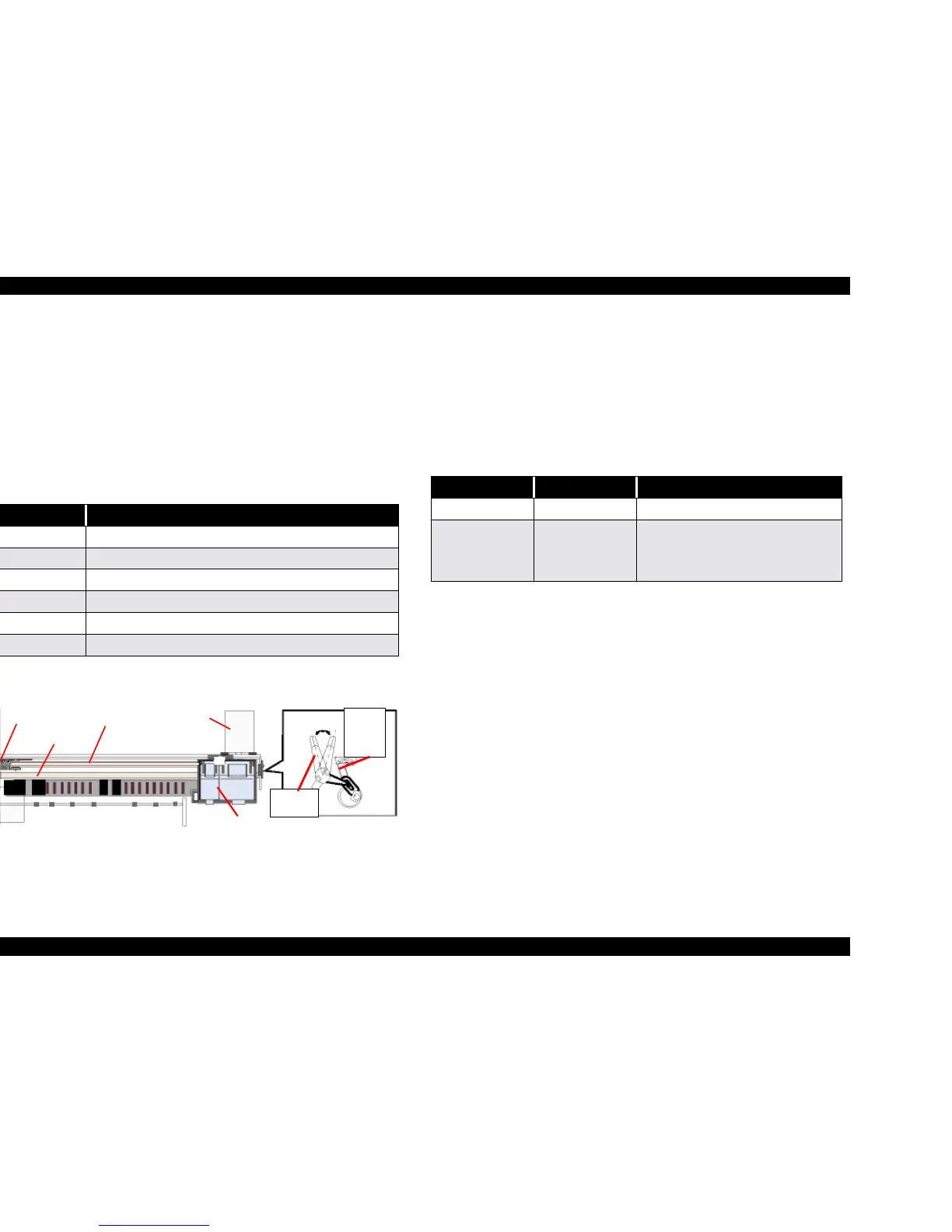
2.1.3 Carriage Mechanism
The carriage mechanism consists of carriage motor (CR motor), carriage unit
(including printhead), CR timing belt, CR guide shaft, CR guide frame, CR
home detector (HP sensor) etc.
The carriage mechanism moves the carriage back and forth according to the
drive from the carriage motor. (See Figure 2-4)
The following stepping motor is mounted to drive CR mechanism. (See the
table below.)
The drive from CR motor is transferred to the CR unit via CR timing belt.
Figure 2-4. Carriage Mechanism (Top view)
2.1.3.1 Platen Gap (PG) Adjustment Mechanism
The PG adjustment mechanism is designed to keep the platen gap correct for
the paper thickness to prevent ink from smearing.
The PG support lever joins the CR guide shaft, which has an eccentricity
toward PG support lever. Switching the lever from “0” to “+” rotates the CR
shaft and changes the platen gap from narrow to wide (within the range of
1.14mm to 2.04mm).
Table 2-2. Carriage Motor
Items Specifications
Type 4-Phase/ 200-Pole HB Stepping motor
Drive Voltage +42 V +/ - 5% (DRV IC voltage)
Coil Resistance 7.8 Ω +/ - 105 (per phase)
Inductance 14 mH +/ - 20%
Drive Method Bi-Polar drive
Driver IC LB11847
PF Roller
Timing Belt
CR motor
CR unit
Right
Parallel
Adjust
Bushing
PG Adjust
Lever
Driven Pulley
Table 2-3. Platen Gap Adjustment
Paper Lever Position PG adjustment value
All Media Front (0) 1.14mm between head and platen
If you find any
print problems or
you use thick
paper.
Rear (+) 2.04mm between head and platen
 Loading...


