EPSON Stylus COLOR 670 Revision A
Operating Principles Electrical Circuit Operating Principles 48
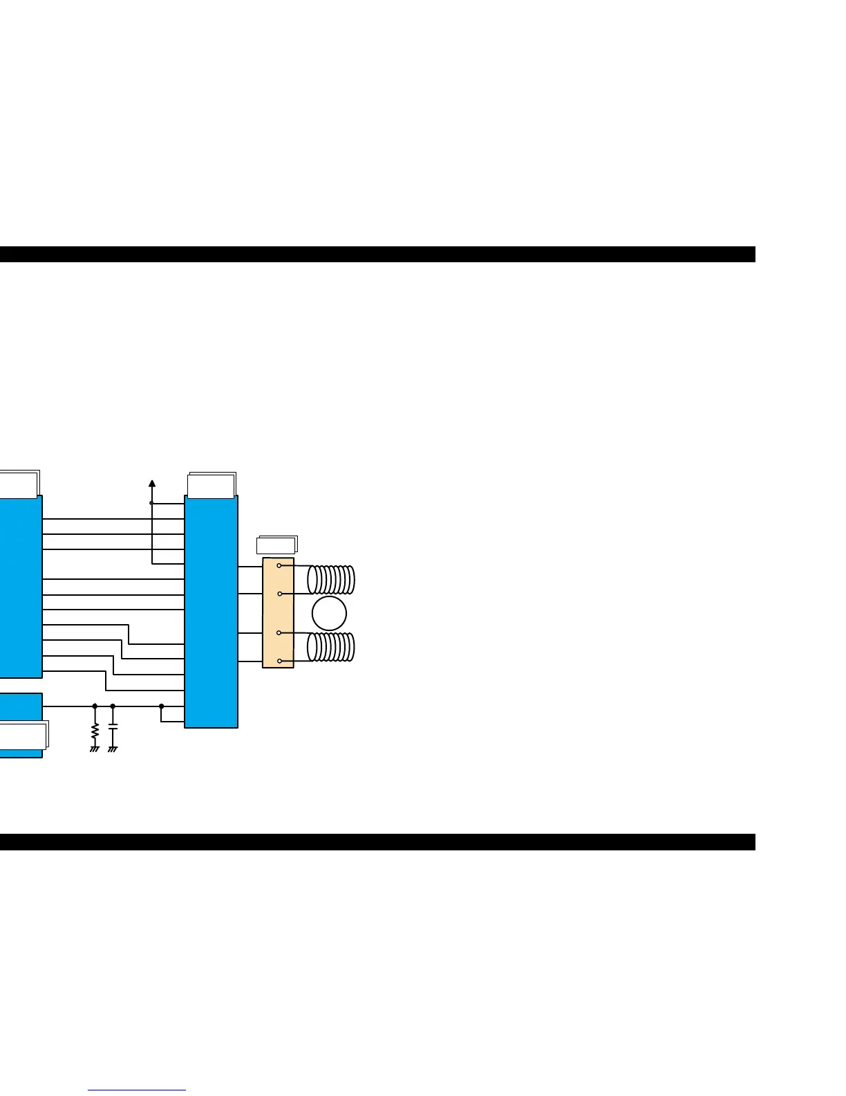
2.2.2.3 PF Motor (PF/ PUMP/ ASF Motor) Driver Circuit
The motor driver IC (IC14) on C301MAIN drives PF/ PUMP/ ASF motor. Stylus
COLOR 670 uses 4-phase 48-pole hybrid type stepping motor and performs
constant current bi-polar drive.
ASIC (IC2) converts PF motor phase control signal to LB11847 micro step
drive form and outputs to motor driver IC (IC14) LB11847 from port 107, 118.
Based on this signal, IC14 determines the phase mode.
The current value on each phase is determined by ASIC (IC2) and outputs
from port 109, 110, 111, 113, 114, 115 to driver IC (IC14). Motor driver IC
generates motor driver waveform based on these input signals and controls
the motor.
Figure 2-15. PF Motor Driver Circuit Block Diagram
DA1
PFENBA
PFENBB
PFPHAA
PFPHAB
108
116
107
118
PFAI1
PFAI2
PFAI3
PFBI1
PFBI2
PFBI3
IA 1
IA 2
IA 3
IA 4
IB 1
IB 2
IB 3
IB 4
PHASE1
PHASE2
ENBL1
ENBL2
Vref1
Vref2
17
2
13
26
16
27
25
24
23
22
18
19
20
21
109
110
111
113
114
115
OUTA
OUTA-
OUTB
OUTB-
7
6
9
8
112
E05B70**
(IC 2 )
H D 64F2328F
(IC 1 )
LB 11847
(IC 14)
Rotor
1
3
2
4
A
A/
B
B/
CN7
+5V
 Loading...


