EPSON Stylus COLOR 670 Revision A
Operating Principles Electrical Circuit Operating Principles 49
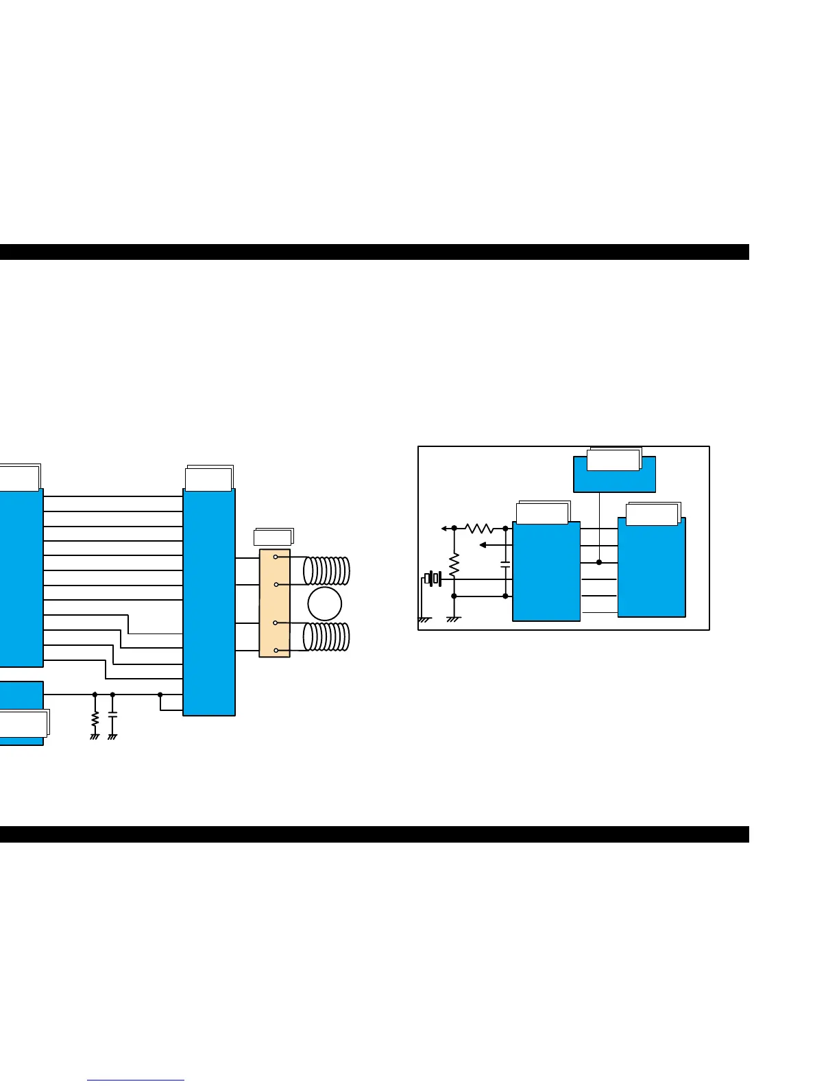
2.2.2.4 CR Motor Driver Circuit
Motor driver IC (IC13) on C301MAIN board drives CR motor.
Stylus COLOR 670 uses 4-phase 200-pole hybrid type stepping motor and
performs constant current bi-polar drive.
ASIC (IC2) converts CR motor phase control signal to LB11847 micro step
drive form and outputs to motor driver IC (IC13) LB11847 from port 93, 105.
Based on this signal, IC13 determines the phase mode.
The current value on each phase is determined by ASIC (IC2) and outputs
from port 95 - 112 to driver IC (IC13). Motor driver IC generates motor driver
waveform based on these input signals and controls the motor.
Figure 2-16. CR Motor Driver Circuit Block Diagram
2.2.2.5 Reset Circuit
Reset circuits consist of reset/ timer IC (IC5) and peripheral elements. Reset
circuits are attached on the C301MAIN board to monitor the two voltages: +5V
for the logic line and +42V for the drive line. When each circuit detects
abnormality on the corresponding line, it outputs a reset signal to reset CPU
(IC1) and ASIC (IC2). This function is necessary to prevent the printer from
operating abnormally. This IC monitors both +5V and +45 lines but can reset
them independently. The reset circuits outputs reset signal when +5V line
becomes 4.3V or lower or +42V line becomes 35.5V or lower.
Reset ICs have built-in timer function, which manages timer control based on
lithium battery.
Figure 2-17. Reset Circuit Block Diagram
Main signal lines are explained below;
n
RST: Reset line
n
CE: Chip enable line
n
VIN: +42V line supervising line
n
VDD: +5V line supervising line
n
VBK: Lithium battery backup voltage line
n
DATA: Timer data line
DA0
CRENBA
CRENBB
CRPHAA
CRPHAB
94
104
9 3
105
CRIA0
CRIA1
CRIA2
CRIA3
CRIB0
CRIB1
CRIB2
CRIB3
IA 1
IA 2
IA 3
IA 4
IB 1
IB 2
IB 3
IB 4
PHASE1
PHASE2
ENBL1
ENBL2
Vref1
Vref2
17
2
13
26
16
27
25
24
23
22
18
19
20
21
9 5
9 6
9 7
9 8
9 9
100
101
102
OUTA
OUTA-
OUTB
OUTB-
7
6
9
8
111
E05B 70**
(IC 2 )
H D 64F2328F
(IC 1 )
LB 11847
(IC 1 3 )
Rotor
1
3
2
4
A
A/
B
B/
CN12
/NMI
MRES
/RESET
/RES
81
10
3
2
140
128
136
+42 VIN
VDD
VBK
GN D
/VDT
FRST
/RST
CE
SCLK
DATA
+5V
BAT1
TDATA
TCLK
TCE
op05
IC5
RTC-9810SA
IC1
HD64F2328F
IC2
E05B570**
 Loading...


