EPSON Stylus COLOR 670 Revision A
Disassembly and Assembly Disassembly 84
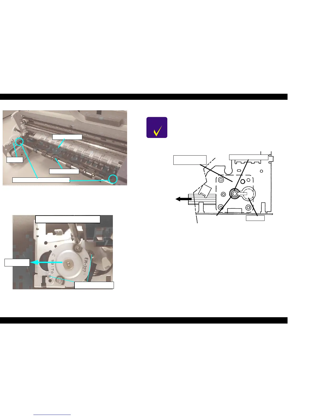
Figure 4-18. Front Paper Guide and Paper Eject Roller Removal
8. Remove 2 screws securing the PF motor from the inside of the Left Frame
and shift the PF Motor Assembly to the front side of the printer to remove
it. (Refer to Figure 4-19.)
Figure 4-19. 2 Screws Securing the PF Motor
Figure 4-20. PF Motor Assembly Installation
Front Paper Guide Securing Hook
Bushing 6
Front Paper Guide
Paper Eject Roller
PF Motor screws
Viewed from inside of the Left Frame
front side
CHECK
POINT
n When removing the PF Motor Assembly, first slightly
pull out the PF Motor Assembly from the frame and slide
the Motor Shaft to a larger cutoff of the frame and
remove it.
n Be careful for the routing direction of the cable from the
PF Motor Assembly. (Refer to Figure 4-20.)
Cable Direction
Small Hole
Large Hole
PF Motor Pinion Shaft
PF Motor
(Behind the Frame)
(Printer rear side)
 Loading...


