EPSON Stylus COLOR 670 Revision A
Disassembly and Assembly Disassembly 86
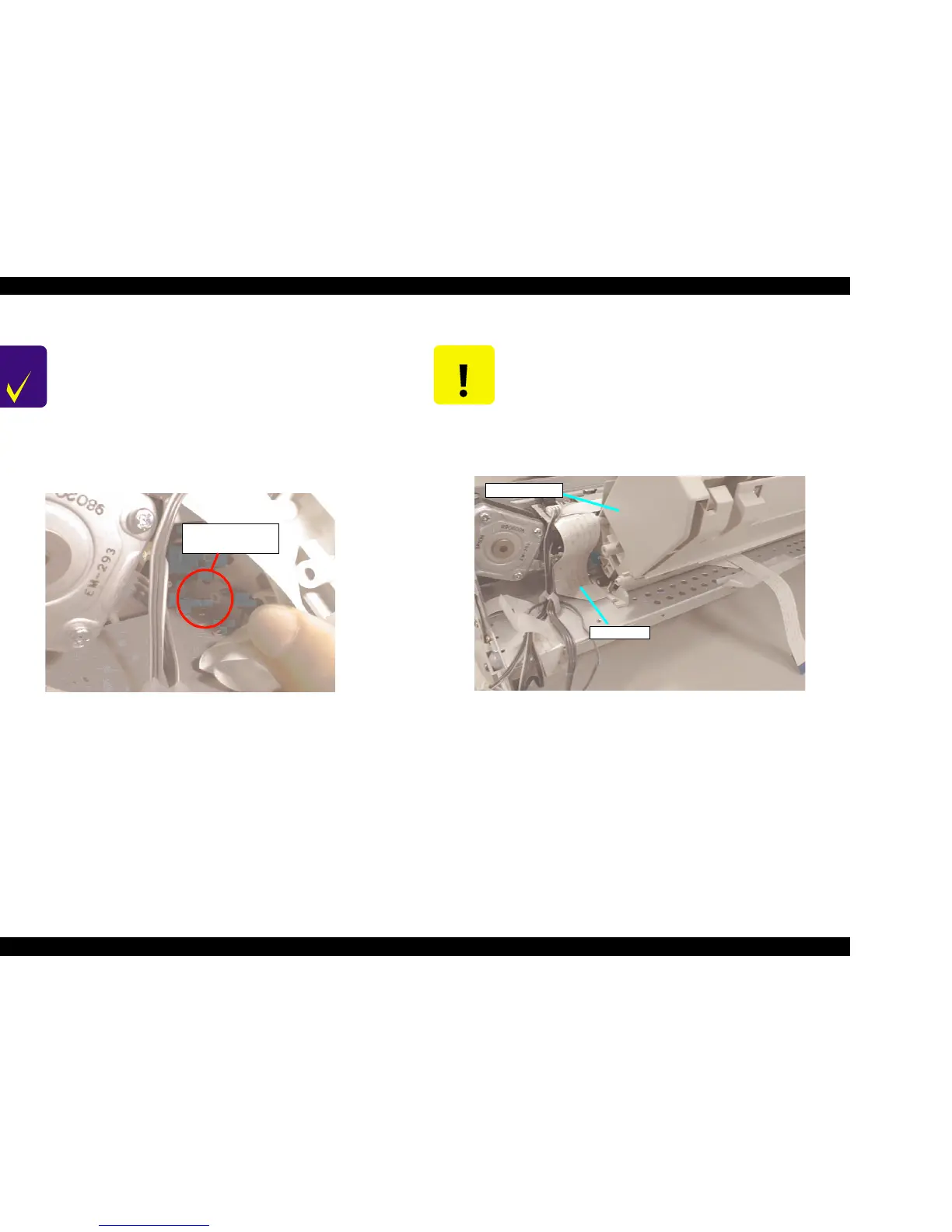
Figure 4-24. ASF Assembly Installation Point Figure 4-25. Head FFC Routing
CHECK
POINT
n When installing the ASF Assembly, make sure that the
protrusion at the right side of ASF Assembly is firmly
inserted to the cutout of the Middle Frame.
n Use the ASF Assembly securing screws at the specified
positions below. (The position is seen from the back side
of the printer.)
*ASF right side: ASF Securing Screw
*ASF left side: Screw with Washer
(Refer to Figure 4-22.)
ASF Left Protrusion
Installation Point
CAUTION
n When installing the ASF Assembly, be careful not to
pinch any motor or sensor cables under the ASF.
Especially if the cables from the motor are pinched, there
is a danger of short-circuit and possibly causes
hazardous problem such as over-heating or burning of
components.
n Head FFC goes under the ASF. When installing the ASF,
be careful not to damage FFC. (Refer to Figure 4-25.)
Head FFC
ASF Assembly
 Loading...


