T3-B T6-B Manipulator 12. Standard I/O Connector
114 T-B series Rev.1
12.2 Output Circuit
Rated Output Voltage : +12 V to +24 V ±10%
Maximum Output Current : TYP 100 mA/1 output
Output device : PhotoMOS relay
ON resistance : Less than 0.7 Ω
The following two wirings are available since non-polar PhotoMOS relay is used for output
circuit.
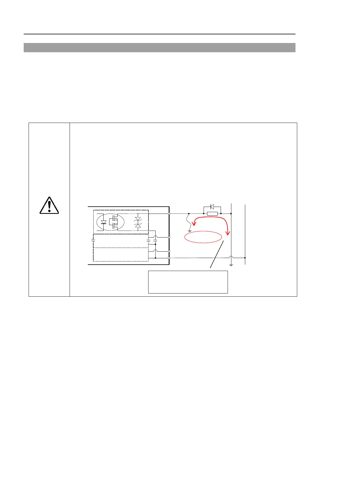
CAUTION
Be sure to wire the output circuit properly because it has no protection circuitry
for short-circuit and reverse-connection. Improper wiring may caus
of the parts on the board and then improper function of the robot system.
To comply with European Machinery Directive, use plus c
ommon (PNP) to
prevent the load from unintended operation in the event of a ground fault in the
wiring between the controller and the load.
Plus common
(PNP) connection
Even if a ground fault occurs,
the current does not flow to
the load and does not operate.

 Loading...


