T3-B T6-B Manipulator 2. Specifications
T-B series Rev.1 41
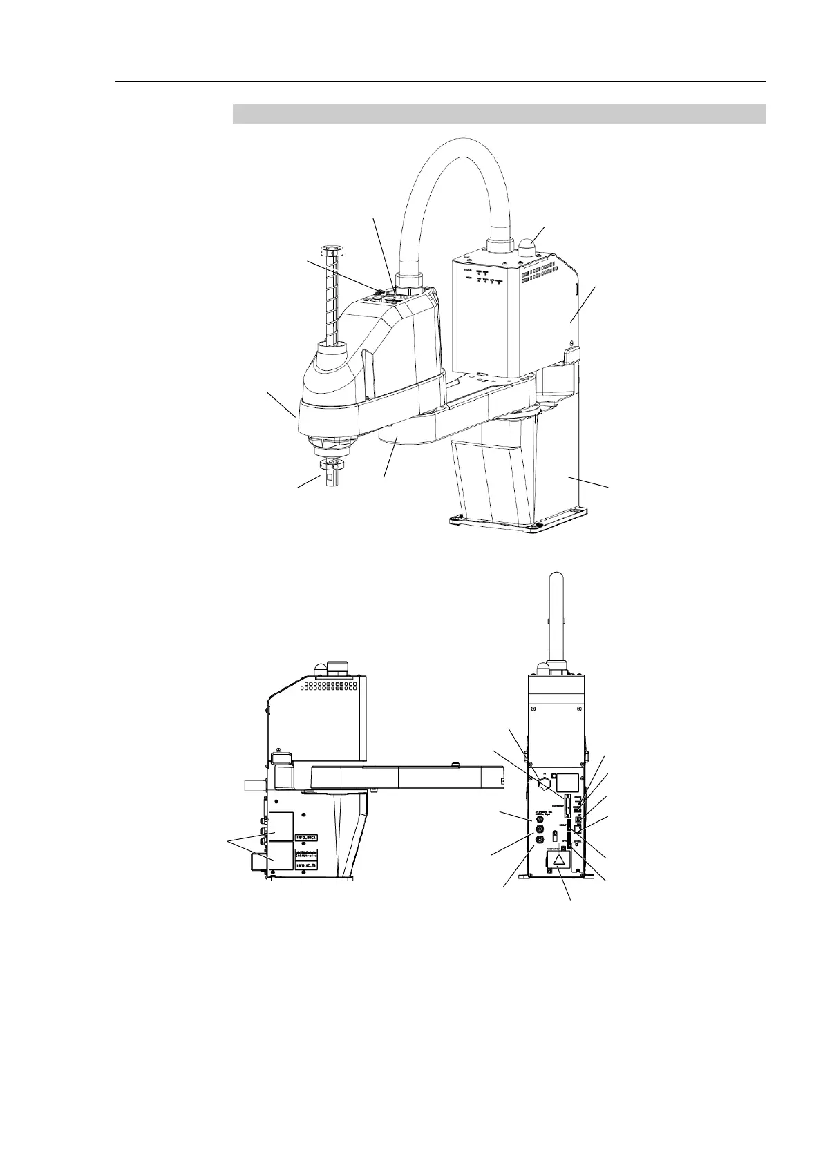
2.2.2 T6-B
Joint #3
Brake Release Switch
Signature label
(Serial No.
of Manipulator)
Fittings (blue)
for ø4 mm
pneumatic tube
Fittings (blue)
for ø6 mm
pneumatic tube
Power Supply Cover
(AC power connector inside)
Port of PC for development
Fittings (white)
for ø6 mm
pneumatic tube
- The brake release switch affects only Joint #3. When the brake release switch is pressed
in emergency mode, the brake for Joint #3 is released.
- While the LED lamp is ON, current is applied to the manipulator. Performing any work
with the power ON is extremely hazardous and it may result in electric shock and/or
improper function of the robot system. Make sure to turn OFF the Manipulator power
before maintenance work.

 Loading...


