T3-B T6-B Manipulator 13. Hand I/O Connector
120 T-B series Rev.1
13.3 Output Circuit
Rated Output Voltage : +12 V to +24 V ±10%
Maximum Output Current : TYP 100 mA/1 output
Output device : PhotoMOS relay
On resistance : Less than 0.7 Ω
The following two wirings are available since non-polar PhotoMOS relay is used for output
circuit.
CAUTION
Be sure to wire the output circuit properly because it has no protection circuitry
for short-circuit and reverse-connection. Improper wiring may cause malfunction
of the parts on the board and then improper function of the robot system.
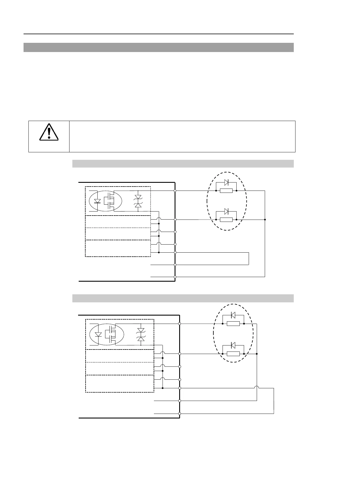
13.3.1 Typical Output Circuit Application 1: Sink Type (NPN)
14 Output No.13
7 Output No.14
15 Output No.15
8 Output No.12 to 15 common (GND)
Do not exceed the
allowable current of
the hand I/O
13.3.2 Typical Output Circuit Application 2: Source Type (PNP)
14 Output No.13
7 Output No.14
15 Output No.15
8 Output No.12 to 15 common
(GND)
Do not exceed the
allowable current of
the hand I/O

 Loading...


