T3-B T6-B Manipulator 5. Motion Range
80 T-B series Rev.1
5.2 Motion Range Setting by Mechanical Stops
Mechanical stops physically limit the absolute area that the Manipulator can move.
Both Joints #1 and #2 have threaded holes in the positions corresponding to the angle for
the mechanical stop settings. Install the bolts in the holes corresponding to the angle that
you want to set.
Joints #3 can be set to any length less than the maximum stroke.
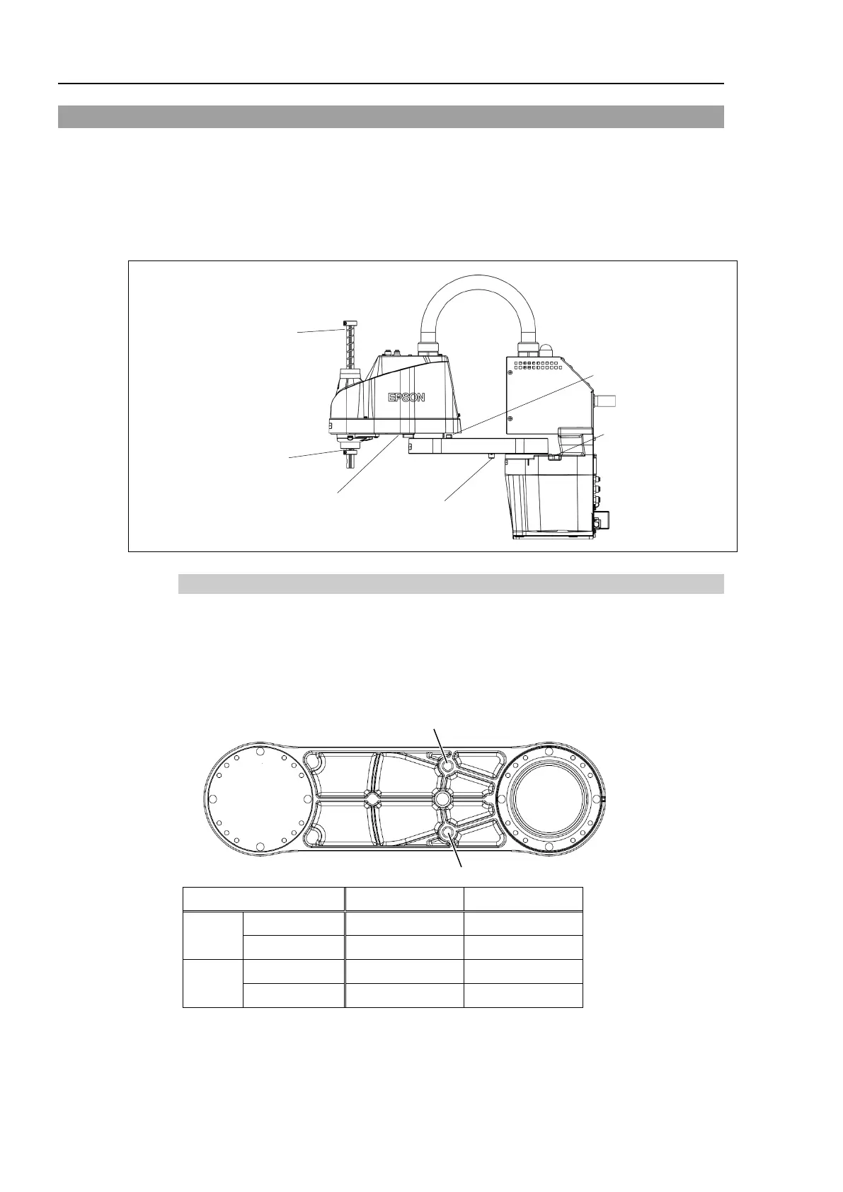
Mechanical stop of Joint #2
(Fixed)
Mechanical stop of
Joint #1 (Adjustable)
Mechanical stop of Joint #3
(Lower limit mechanical stop)
(Do not move the upper
limit mechanical stop.)
Mechanical stop of
Joint #1 (Fixed)
Mechanical stop of
Joint #2 (Adjustable)
5.2.1 Setting the Mechanical Stops of Joints #1 and #2
Both Joints #1 and #2 have threaded holes in the positions corresponding to the angle for
the mechanical stop settings. Install the bolts in the holes corresponding to the angle that
you want to set.
Install the bolts for the mechanical stop to the following position.
Joint #1 Mechanical Stops (Views from the bottom of Arm #1)
T3-B
°
−
°
−
T6-B
°
−
°
−

 Loading...


