T3-B T6-B Manipulator 5. Motion Range
82 T-B series Rev.1
6)
perate the joint changed at low speeds until it reaches the positions of the
maximum pulse range.
Make sure that the arm does not hit the mechanical stops.
(Check the
position of the mechanical stop and the motion range you set.)
The angle of Joint #1 is set from -110° to +110°.
The angle of Joint #2 is set from -120° to +120°.
Execute the following command
s from the [Command Window].
>MOTOR ON ' Turns ON the motor
>POWER LOW ' Enters low-power mode
>SPEED 5 ' Sets at low speeds
>PULSE -45512,0,0,0 ' Moves to the min. pulse position of Joint #1
>PULSE 455112,0,0,0 ' Moves to the max. pulse position of Joint #1
>PULSE 204800,-273066,0,0 ' Moves to the min. pulse position of Joint #2
>PULSE 204800,273066,0,0 ' Moves to the max. pulse position of Joint #2
The Pulse command (Go Pulse command) moves
all joints to the specified positions
Specify safe positions after considering motion of not only the joints
whose pulse range have been changed, but also other joints
.
In this example, Joint #1 is moved to the
center of its motion range
(pulse value:
204800) when checking Joint #2.
is hitting the mechanical stop
s or if an error occurs after the arm hits the
mechanical stops
, either
reset the pulse range to a narrower setting or extend the
positions of the mechanical stops within the limit.
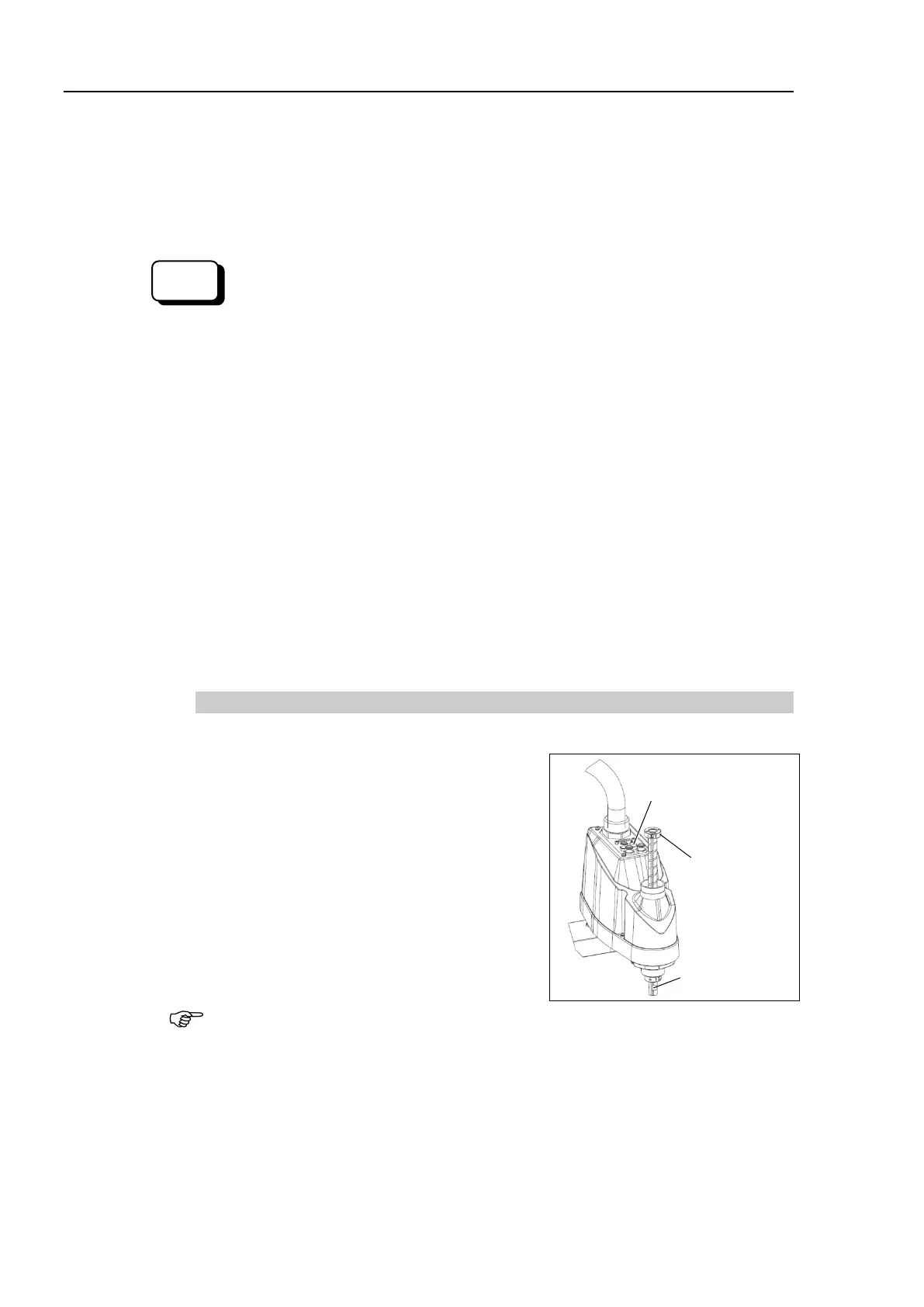
5.2.2 Setting the Mechanical Stop of Joint #3
1)
Turn ON the Manipulator and turn OFF the motors using the Motor OFF command.
2)
Push up the shaft while pressing the brake
release switch.
shaft up to its upper limit or it
will be difficult for the arm top cover to be
removed.
Push the shaft up to a position where
the Joint #3 mechanical stop can be changed.
Lower limit
mechanical
stop screw
T3-B:
M3×10
T6-B:M4×15
the brake release switch, the shaft may lower due to
the weight of the
end effector.
Be sure to hold the shaft by hand while pressing the button.
3)
Manipulator.
Loosen the lower limit mechanical stop screw
(T3-B: M3×10, T6-B: M4×15).

 Loading...


