Model 5601MSC
Model 5601MSC Master SPG/Master Clock System
OPERATION Revision 2.2 Page - 17
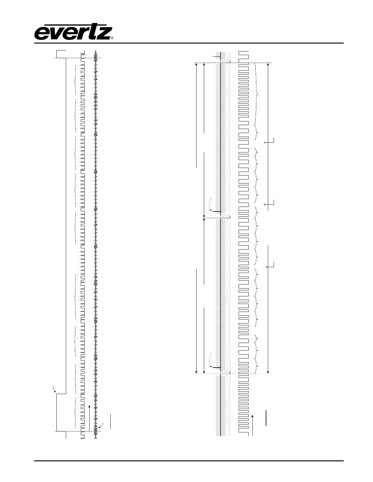
Figure 2-2: IRIG-B127 Format and Alignment to IRIG1 Datum Pulse
Figure 2-3: 29.97Hz LTC Format and Alignment to NTSC Video
P
r
P
0
1 0 M P
1
1
0 1 0 1
Seconds
1 1 10 0 0
0M M P
2
1 100 0 0
M M P
3
1
1 10 0 0M P
4
M M P
5
10 0 0 0M P
6
0 0 0 0
P
7
0 0 0
P
8
Minutes
Hours
0
Days
1 0 1 1
Year
M M M MM 0 0
0 0 0 0 0 0 00 0 0 0 0
Control Bits 1
-9 Control Bits 10-18
0 0 P
9
0 0
Straight Binary
Seconds Bits
0-8
1 1 1 1 1 0 0
Straight Binary
Seconds Bits 9-17
11 10
0 0 M
IRIG1 Datum Pulse
IRIG Output – Amplitude Modulated 1kHz Sinewave
P
0
IRIG-B127 – 100 bits/
second
LEGEND
Pr
= Reference Bit
P
0
… P
9
= Position Identifier Bits
M
= Index Marker Bit (always 0
)
29.97Hz LTC
VITC field 1 line 14
Field 1
NTSC Black Burst - One Frame (33.367ms)
Field 2
VITC field 2 line 14
Sync Word
1
Frames
1 1 0 0
BG1
0 0 0 0 0
10Fr
1 1 1 0 1 0 1 0 1 0
BG2
Seconds BG3
0 1 0 0 1 0 1
10sec
1
BG4
0 1 1 0
Minutes
0 0 0 1
BG5
0 0 0 0 1 1 0
10min
0
BGF0
BG6
0 0 0 0
Hours
1 0 0 0
BG7
0 0 0 0 1 0
10Hr
0 0
BG7
1 0 0 0 0 0 1 1 1 1 1 1 1 1 1 1 1 1 0 1
BGF1
BGF2
Pol. Cor.
Drop Fr.
Color Fr.
29.97Hz LTC = 2397.6 bits/second
LEGEND
BG# = Binary Group (User Bits)
Drop Fr. = Dropframe Counting Flag
BGF# = Binary Group Flags
Color Fr. = Color Frame Alignment Flag
Pol. Cor. = Bit used for Polarity Correction
BGF0 in 25Hz BGF2 in 25Hz
Polarity Correction in 25Hz