Model 5601MSC
Model 5601MSC Master SPG/Master Clock System
INSTALLATION Revision 2.2 Page - 57
3. INSTALLATION
3.1. REAR PANEL
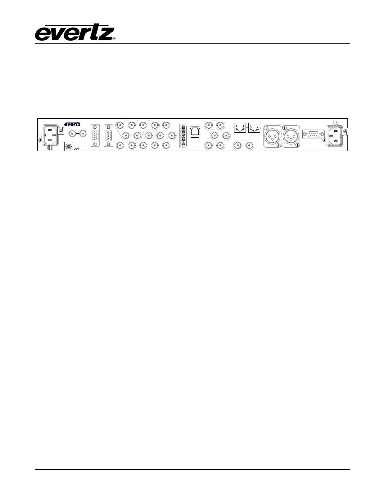
Figure 3-1 provides an illustration of the 5601MSC rear panel. The following sections describe the
purpose of the rear panel connectors of the 5601MSC. The following sections 3.1.1 to 3.1.11 describe
the specific signals that should be connected to the 5601MSC.
Figure 3-1: 5601MSC Rear Panel
3.1.1. Reference Loop Connections
The two REF IN LOOP BNC connectors provide a reference loop input for black burst, tri-level, and
5MHz/10MHz signals. The BNCs are isolated from chassis ground. The frequency reference source
must be set to Video in order to genlock to black burst or tri-level video signals. It must be set to 10MHz
in order to lock to 5MHz or 10MHz reference signals. See section 4.3 for more information. The loop is
high impedance and will need to be properly terminated with 75 ohms using an external termination.
3.1.2. Sync Outputs
SYNC 1 to 6 - These BNC connectors provide six independent programmable sync outputs that are
configured by the SYNC 1 to SYNC 6 group of sub-menus in the OUTPUT setup menu. Each output
can be configured for any format of sync output from black burst, to tri-level, to 5MHz/10MHz, to
wordclock, and more. See section 4.4.2.
10 MHz OUT - This BNC connector provides a 10MHz frequency reference but can also be
programmed as another sync output. It is recommended that this output be configured as a 10MHz
output when used in conjunction with a 5601ACO2 to simplify wiring. It is configured using the 10 MHz
sub-menu in the OUTPUT setup menu.
WORDCLOCK - This BNC connector provides a 48kHz wordclock signal but can also be programmed
as another sync output. It is recommended that this output be configured as a wordclock output when
used in conjunction with a 5601ACO2 to simplify wiring. It is configured using the Wordclock sub-menu
in the OUTPUT setup menu.
MODEL 5601MSC
REF IN LOOP
GPS GPIO
MODEM
AUDIO
TIME CONTROL
LTC / IRIG
OUTPUT 1
COM
GND
TG1-2
10/100 LN/ACT 10/100 LN/ACT
TG2-
1 TG2-2
TG3-1 TG3-2
TG4-1 TG4-2
TG1-1
SYNC1
SYNC
2
SYNC
3
SYNC4 WORDCLOCK
10MHz
SYNC5 SYNC6
ATG1
ATG2
DARS
AUX IN AUX OUT
AES1 AES2
(A)
(B)
(A) (B)
(A)
(B)
(A)
(B)
LTC / IRIG
OUTPUT 2