4. Maintenance
USE AND MAINTENANCE MANUAL CHAPTER 4
MAINTENANCE2-Strokes - Edition 00 / 2023
124
1
2
a
3
1
2
b a
34
1
ba
2
1
2536 5 3
4 4
a
1
1
2
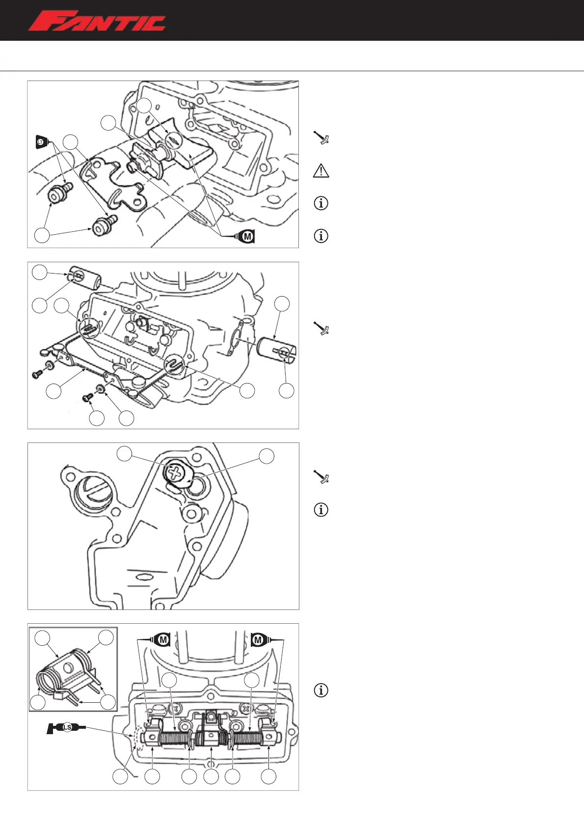
– Install springs “1” on the connection lever “2”. The “a” arms
of the springs must face inwards, as shown in the figure.
– Install the exhaust valve shaft in the cylinder, inserting on it
the linkage lever “2” with springs, the linkage rod, washers
“5”, springs “4” and pulleys “3”.
Apply lithium soap-based grease to the lip of oil seal
“6”.
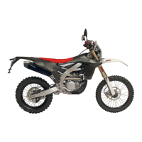
Exhaust valve installation (XX 250 version)
– Install the main exhaust valve “1”;
– Install the secondary exhaust valve bracket “2” and bolts
“3”
Valves bracket fastening bolt:
6 Nm (0.6 m•kg, 4.4 ft•lb)
Install the exhaust valve with notch “a” facing
upwards.
Apply molybdenum disulphide oil to the surface of
the exhaust valve.
Apply threadlocker to the secondary valves bolts.
– Install the secondary exhaust valves “1”;
– Install the linkage rod “2”, inserting the forks “a” at its ends
into the pins “b” of the secondary valves;
– Install washers “3”;
– Install the linkage rod screws “4”.
Bolt (link lever):
6 Nm (0.6 m•kg, 4.4 ft•lb)
– Install the thrust plate “1” and its fastening screw “2” on
the cylinder.
Thrust plate screw:
6 Nm (0.6 m•kg, 4.4 ft•lb)
Be sure to install the thrust plate before installing
the exhaust valve shaft.