A. Technical appendix
A−18
Festo P.BE−CPEA−CL−EN en 0711a
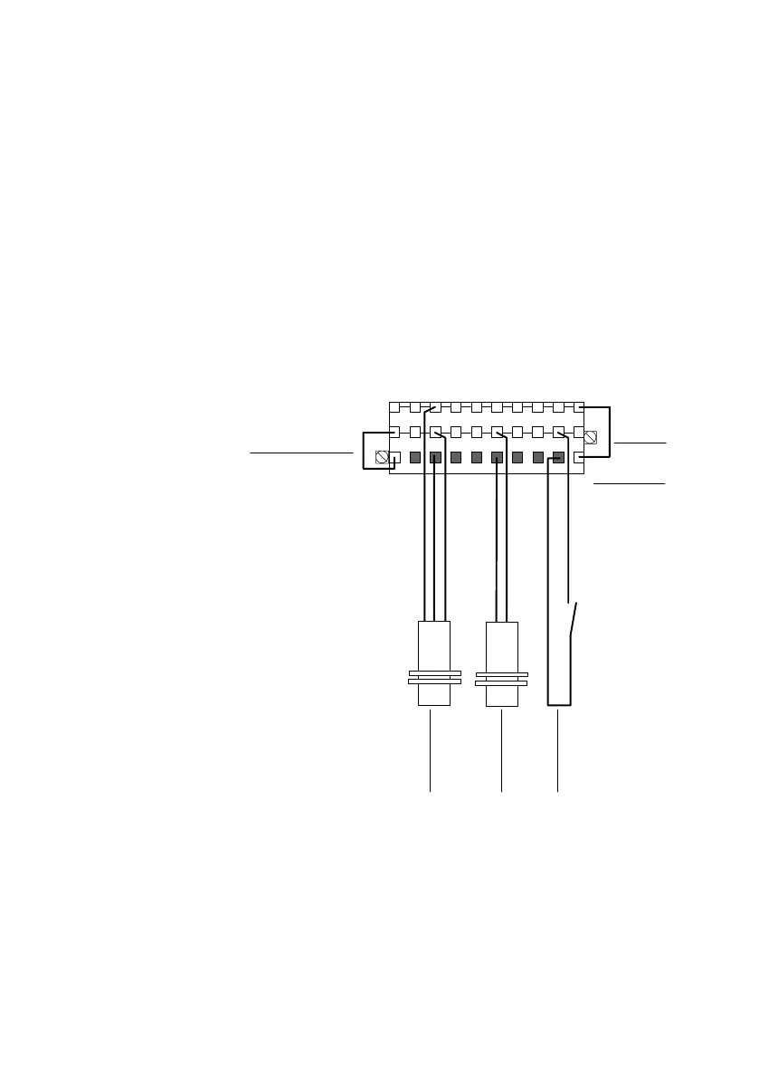
Circuitry example type CP−E16−KL−CL
Two rows of the three−row connector socket are intended as
distributor boards for the sensor supply. These rows are each
connected internally. The upper row (blue pushbuttons) is
intended for the 0 V distributor; the centre row (red pushbut
tons) is intended for the 24 V distributor. The relevant volt
age must be
supplied by means of an external bridge from
the terminals + and (lower row).
1 External bridge for
pot e nt i a l
dis t ri but i o n (24 V)
2 External bridge
for potential
distribution (0 V)
3 Pin assignment
+: 24V
0 ... 7: Ix+n
: 0V
4 Contact
5 Two−wire sensor
(positive−switching)
6 Three−wire se nsor
(positive−switching)
Ix = Input x
1
4
+ 0 1 234
5
67
2
3
56
+
−
red = +
blue = −
Fig.A/8: Circuitry example type CP−E16−KL−CL
with 3−row connector set type CP−E16−KL−CL
 Loading...


