A. Technical appendix
A−23
Festo P.BE−CPEA−CL−E N en 0711a
Method of operation
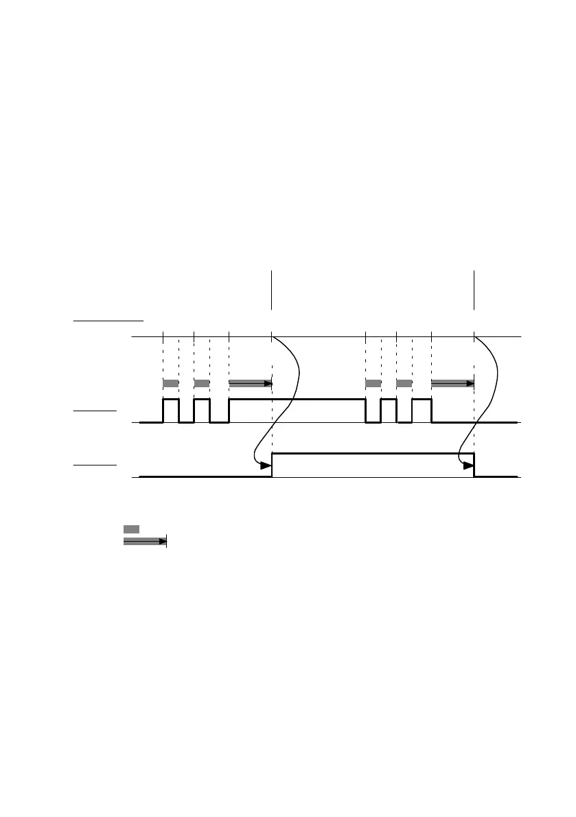
Changes of edge in the sensor signal will be accepted as
a logical input signal (see Fig.A/1) only when the specified
debouncing time has expired.
Dependency diagram
1
22
3
4
0
1
0
1
Start = debouncing time started
End = debouncing time completely expired
Sensor signal is unstable (shorter than debouncing time)
Sensor signal is sufficiently stable (= debouncing time)
Start Start StartStartStartStart End End
1 Start and end (sequence) of the
debouncing time
2 Debouncing time has expired
3 Sensor signal
4 Logical CPI signal
Fig.A/1: Input debouncing
 Loading...


