3. Electrical installation
3−10
Festo P.BE−CPX−CMA X−SYS−EN en 0908NH
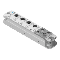
CASM−S−D3−R7 Sensor interface for digital, incremental displacement encode rs
with M12 displacement encoder connection (socket, 8 pin).
Pin
Allocation S2
1 + Ub sensor (5 V)
7
2 0 V
1
6
3 Sine signal +
5
8
4 Sine signal
4
2
5 Cosine signal
3
6 Cosine signal +
7 Screen
8 n.c. (not connected)
Housing Earth terminal (FE)
The cable screening is connected to the earth terminal of the sensor
interface.
Tab.3/7: Pin allocation of connection S2 for the CASM−S−D3−R7
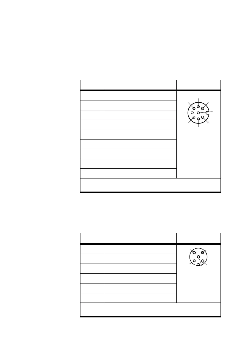
CASM−S−D2−R3 Sensor interface for analogue, absolute displacement enco de rs
(potentiometer), with M12 displacement encoder connection
(socket, 5 pin).
Pin
Allocation S2
1 Displacement encoder housing
3
4
2 n.c. (not connected)
3 Analogue GND (AGND)
2
1
5
4 Reference voltage 5 V (REF 5V)
5 Analogue input 0 ... 5 V (INPUT)
Housing Earth terminal (FE)
The cable screening is connected to the earth terminal of the sensor
interface.
Tab.3/8: Pin assignment of connection S2 for the
CASM−S−D2−R3

 Loading...