3. Electrical installation
3−12
Festo P.BE−CPX−CMA X−SYS−EN en 0908NH
3.4 Power supply
The power for the positioning system with the CMAX is
supplied via the following connections on the CPX terminal
(interlinking blocks with voltage input):
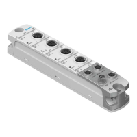
Interlinking block
CPX−EV−S... or
CPX−M−EV−S... (U
EL/SEN
)
The following is supplied with power via the operating
voltage supply for the electronics/sensors (U
EL/SEN
) of the
CPX terminal:
Internal electronics of the CMAX
Internal electronics of the VPWP
Connected sensor interface (optional)
Connected position measuring system.
Interlinking block
CPX−EV−V..., CPX−M−EV−V...,
CPX−EV−S... or
CPX−M−EV−S... (U
VAL
)
Power is supplied to the following via the valve load supply
(U
VAL
) of the CPX terminal:
24 V load supply of the VPWP
Brake output (digital output) of the VPWP.
Note
Operative malfunctions due to power supply outside the
tolerance.
The module with the lowest tolerance always determines
the permissible voltage tolerances.
· If the CMAX is used, special tolerances according to
Tab.3/9 must be obser ved for the valve load supply
(U
VAL
) of the CMAX.
Valve load supply (U
VAL
) Range
CMAX 20 ... 30 V
1)
1)
If midi/maxi pneumatics are also supplied via the valve load sup
ply: 21,6 ... 26.4 V
Tab.3/9: Permissible voltage tolerance

 Loading...