3. Electrical installation
3−18
Festo P.BE−CPX−CMA X−SYS−EN en 0908NH
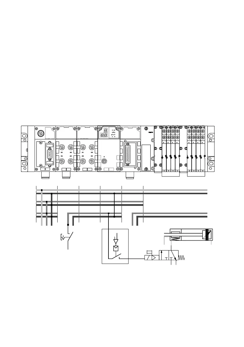
3.4.3 Disconnecting the load voltage in connection with a brake or
clamping unit
In the example, circuitry for a brake or clamping unit is con
nected to the brake output. When switching off, or when the
CMAX valve load supply drops out, the brake or clamping unit
is activated.
8DI
8DI4DO
CMAX
8 A8 A
1
MPA
2
Schematic representation:
3
24V
VAL
0V
VAL
24V
OUT
0V
OUT
24V
EL/SEN
0V
EL/SEN
1 Brake output of the VPWP proportional directional control valve
2 Activation/deactivation of the brake/clamping unit by the CMAX
3 Activation of the brake/clamping unit by switching off the load voltage
Fig.3/4: Switching off the load voltage supply of the brake output at the VPWP together
with the valve load supply (example)

 Loading...