3. Electrical installation
3−5
Festo P.BE−CPX−CMAX−SYS−EN en 0908NH
3.2 Axis interface
The VPWP proportional directional control valve is connected
to axis interface ’X’ of the CMAX. The position measuring sys
tem or a sensor interface (depending on the displacement
encoder) is connected to the VPWP.
This forms an axis string.
The axis interface pin allocation for the CMAX, VPWP and sen
sor interface are shown
in Tab.3/2.
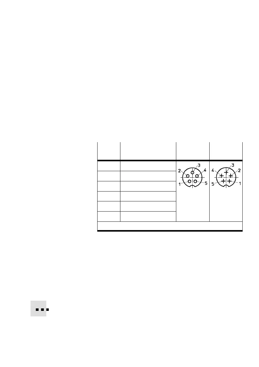
Pin
Allocation CMAX: X
VPWP: Out
VPWP: In
CASM: S1
1 + 24 V operating voltage
2 + 24 V load voltage
3 0 V
4 CAN_H
5 CAN_L
Housing Cable shield
1)
1)
Connect each VPWP cable shield to the earth terminal
Tab.3/2: Pin allocation of the axis interfaces
Line length
The maximum permissible line length (total) of the
KVI−CP−3−... connecting cables of the axis string is 30m
(total length CMAX VPWP sensor interface or displace
ment encoder).
Tab.3/3 shows the recommended connecting cables.

 Loading...