3. Electrical installation
3−7
Festo P.BE−CPX−CMAX−SYS−EN en 0908NH
3.2.1 VPWP proportional directional control valve
The VPWP has one incoming (In) and one outgoing (Out) axis
interface. See Tab.3/2.
Digital output DO (brake) A digital output (DO) at pin 2 is also available for controlling
a valve for a brake or clamping unit. This is controlled via the
CMAX I/O data (see section 4.5).
Note
For the control via CMA X to function correctly, it is compul
sory that the clamping unit or brake be connected with the
following logic (see also section 3.4.3, Fig.3/4):
Pin 2: 0 V = clamping unit/brake closed
Pin 2: 24 V = clamping unit/brake open
Voltage output
(load voltage)
The load supply voltage
provided at pin 4 can also be used
for switching a valve when the load supply voltage V
VAL
fails,
for example. See section 3.4.3.
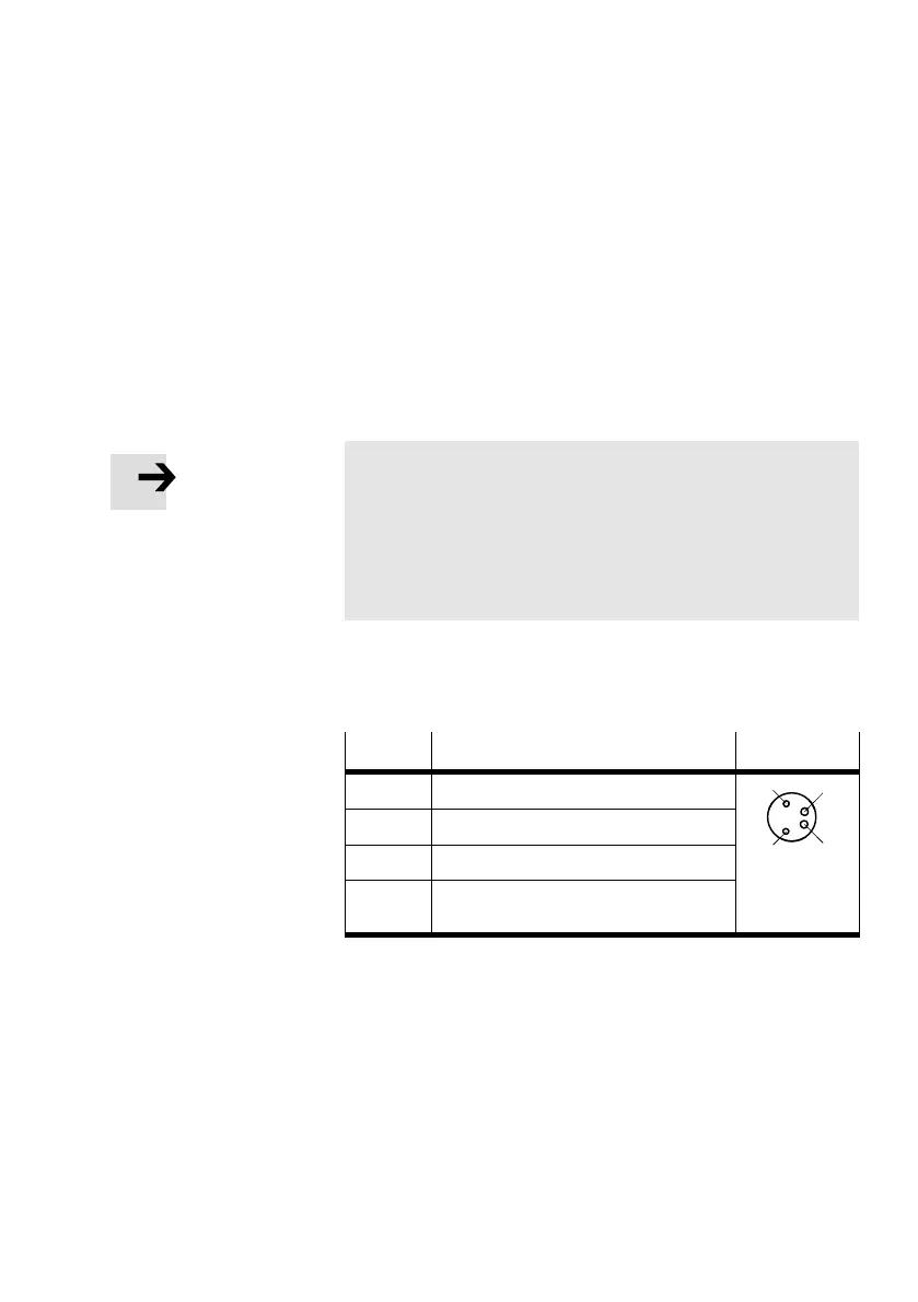
Pin
Allocation DO
1 n.c. = (not connected)
4
3
2 Digital output (brake)
3 0 V
21
4 + 24 V voltage output
(load voltage)
Tab.3/4: Pin allocation DO connection of the VPWP,
M8 4−pin, socket

 Loading...