5 | Operation FISCHER Mess- und Regeltechnik GmbH
74/108 BA_EN_FT90
5.5.1.5.3 Colour change C1 hysteresis
Path: \Configuration\Channel 1\Colour change C1\Col.ch. C1 hyst.
Level: 4
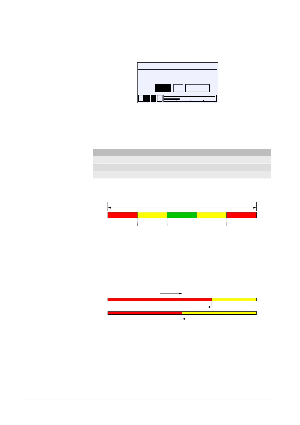
Col.ch. C1 hyst.
1 2 3 4
OK CancelEdit
10.000
Pa
U
Fig.106: Colour change C1 hyst.
This parameter can be used to define an hysteresis for the switch thresholds of
the colour change. The set hysteresis applies to all switch thresholds at the
same time. The input is a pressure value in the current unit. The allowed value
range is stated automatically.
Functional principle: The colour symbolises the following risk levels:
Colour Risk level Operating mode
Green 0 Normal
yellow 1 Warning
rot 2 Danger
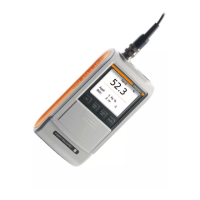
The following colour change red/yellow/green is examined as an example for all
colour changes. There are a total of four switch thresholds (S1...S4) in which a
colour change is realised. This leads to the following image without hysteresis.
Risk level
Switching thresholds
Measuring range
RED REDYELLOW YELLOWGREEN
2 1 0 1 2
S1 S2 S3 S4
Fig.107: Colour change (without hysteresis)
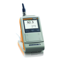
The parameter Col.ch. C1 hyst. defines a distance to the switch threshold.
The colour change with hysteresis is then realised as follows:
(i) Lower switching thresholds S1 and S2
In case of a colour change from a higher to a lower risk level, the hysteresis
acts with an increasing signal.
S1
+ 0.5
Increasing signal
Falling signal
Fig.108: Example: Hysteresis S1