FLEX-6000 Signature Series – Maestro User Guide
Copyright 2024 FlexRadio, Inc. All Rights Reserved. | Page 20
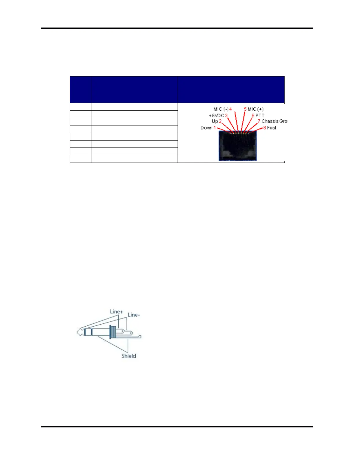
4.4.9 Maestro “A” and “B” Mic 1 Connection
The 8-pin RJ-45 MIC 1 connector offers the ability to connect a microphone and to key the radio via
a PTT line. The RJ-45 pin-out is shown below. To engage PTT, pin 6 must be grounded to pin 7
(Shield Ground) and not to pin 4, which is the microphone ground.
+5 VDC (470 Ohm
Impedance)
Chassis Ground for
Shield/PTT
To prevent ground loops and RF ingress into the microphone circuit, the MIC (-) wire should be
connected to pin-4 only and NOT be connected to the pin-7 chassis ground. The microphone circuit
is wired as pseudo-differential and can thus be used with balanced or unbalanced microphones as
long as the MIC (-) wire connects only to pin-4. Bias for electret microphones may be derived from
the +5 VDC output on pin-3.
Although Maestro will work well with many types of microphones, it is wired for the convenient use
of microphones such as the FlexRadio FMH-3-RJ45. The FHM-3-8P hand microphone supplied with
the FLEX-6000 Series Radios uses an 8-pin Foster connector. This microphone may be adapted to
Maestro with either the ACC-ADM817 RJ45 to 8-pin Male Foster Adapter cable or the ACC-CLV-310
RJ45 to RJ45 coiled cable replacement.
4.4.10 Maestro “A” and “B” Line In Connection
The LINE-IN connector accepts a 1/8-inch (3.5mm) stereo (TRS) plug and provides a pseudo-
differential line level input to the transmitter.
 Loading...