Limitorque MX Maintenance and Spare Parts FCD LMENIM2314-00 – 07/08
124
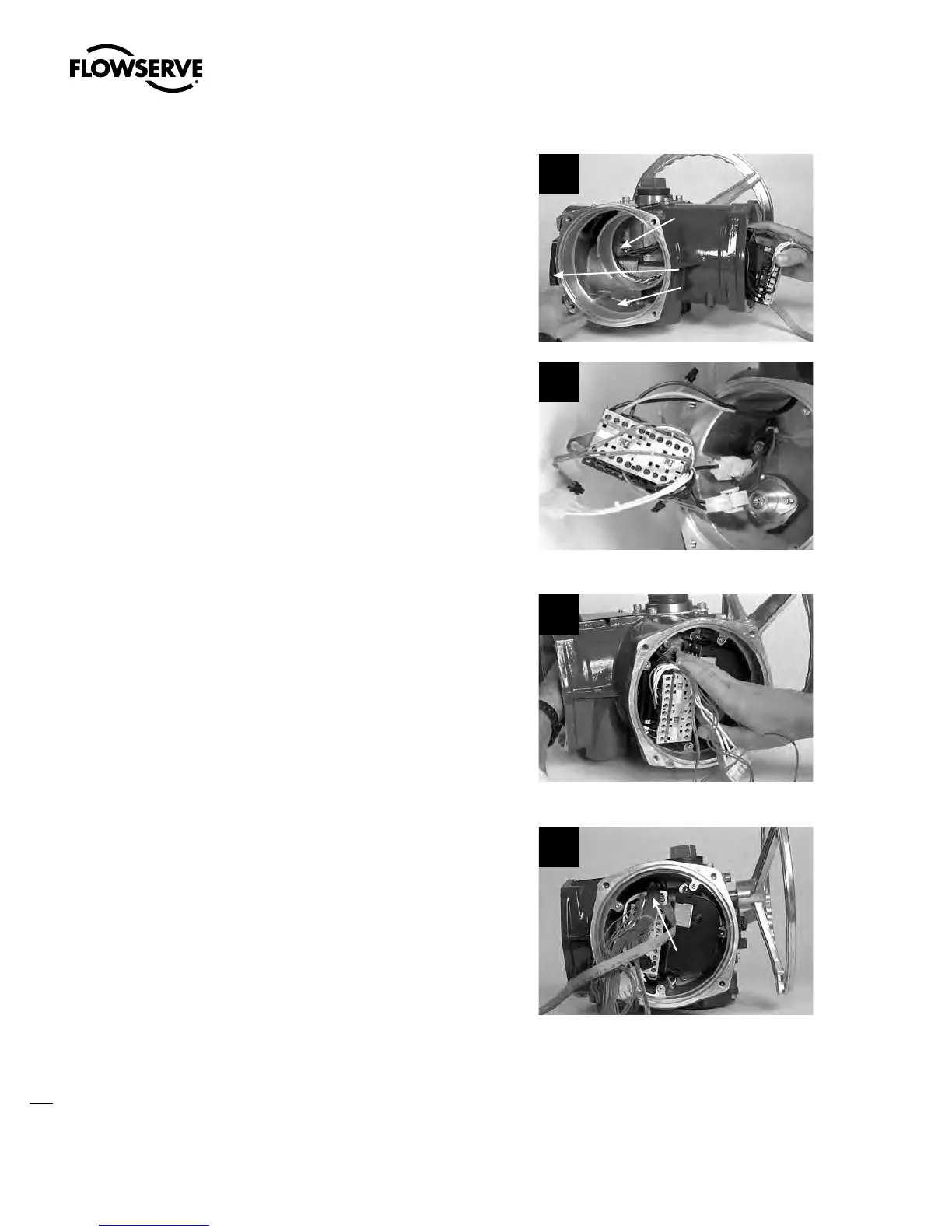
STEP 5
Route leads L1, L2, and L3 (input power) to the
terminal block cavity.
MX-05, -10, -20 AND -40 ONLY
Feed the motor power plug through the
housing to the motor cavity.
MX-85, -140, AND -150 ONLY
Reconnect connectors 4 and 5 to the motor
lead harness.
5a
Motor Cavity
Terminal Block
Cavity
Motor Power
Plug
5b
STEP 6
Leave the contactor assembly unmounted in
the control module compartment to allow space
for the terminal block harness plug bundle to be
threaded over the top of the contactor assembly
and pulled into the control module cavity.
6
STEP 7
Reference the terminal block assembly proce-
dures to remount the terminal block assembly
into actuator. (See Section 5.8.2.)
Before mounting the contactor assembly,
ensure the terminal block wiring harness
bundle is positioned across the end of the
contactor.
7
Terminal Block
Wiring Bundle
Swanson Flo | 800-288-7926 | www.swansonflo.com