5
Limitorque QX Electronic Actuator FCD LMENIM3306-06 – 07/14
flowserve.com
Figures
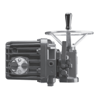
Figure 1.1 – QX-05 Actuator 7
Figure 2.1 – Electrical operation 12
Figure 2.2 – Handwheel operation 14
Figure 2.3 – QX travel stops 14
Figure 3.1 – Top view - stem nut with standard keyway position 17
Figure 3.2 – Exploded view of QX bases 17
Figure 3.3 – Power terminal connector size limitations 19
Figure 3.4 – Terminal block 20
Figure 3.5 – Control terminal connector size limitations 20
Figure 3.6 – View of terminal block 22
Figure 3.7 – Standard wiring diagram - three phase shown 23
Figure 3.8 – Removing outer plastic jacket 23
Figure 3.9 – Separating cable parts 24
Figure 3.10 – Stripping conductors and applying heat shrink tubing 24
Figure 3.11 – Ring tongue connectors 24
Figure 3.12 – Terminal block shield 28
Figure 3.13 – User network connection for loop topology 29
Figure 3.14 – External earth/ground connection – housing 29
Figure 3.15 – View settings 31
Figure 3.16 – Position setup – electrical operation 33
Figure 3.17 – Declutch lever shows direction of engagement (QX-05 shown) 34
Figure 3.18 – Control panel 35
Figure 4.1 – Entering the setup mode 38
Figure 4.2 – Main menu selections 38
Figure 4.3 – Changing settings 39
Figure 4.4 – Password entry 40
Figure 4.5 – New password 40
Figure 4.6 – Valve setup 41
Figure 4.7 – Torque switch timer 42
Figure 4.8 – Operating Time Setup 43
Figure 4.9 – Torque setup 43
Figure 4.10 – Typical XP nameplate 44
Figure 4.11 – Electrical operation 46
Figure 4.12 – Handwheel operation 46
Figure 4.13 – Modutronic option 48
Figure 4.14 – Modutronic signals 49
Figure 4.15 – DDC 50
Figure 4.16 – Foundation Fieldbus 53
Figure 4.17 – Profibus DP 54
Figure 4.18 – Profibus PA 55
Figure 4.19 – DN Option 57
Figure 4.20 – Status and alarm contacts (Shown with optional boards added) 59
Figure 4.21 – Two-speed timers 60
Figure 4.22 – Change Analog Out 61
Figure 4.23 – Change Analog Out Voltage – APT 61
Figure 4.24 – Change Analog Out Current – APT 61
Figure 4.25 – Change Analog Out Voltage – ATT 62
Figure 4.26 – Change Analog Out Current – ATT 62
Figure 4.27 – Remote mode 63
Figure 4.28 – Local control 64
Figure 4.29 – ESD Overrides 65
Figure 4.30 – Inputs 68
Figure 4.31 – Custom Input Mode 70
 Loading...

