9
2-3. PC Network Settings
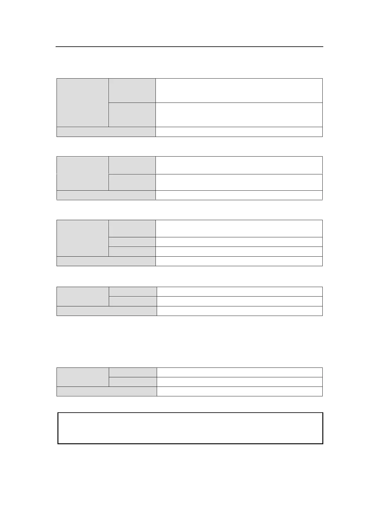
MFR series factory default port settings are as follows.
MFR-5000/8000
192.168.1.10 (CPU CARD1)
192.168.1.11 (CPU CARD2)
(with an optional MFR-CPU installed)
192.168.1.12 (CPU CARD1)
192.168.1.13 (CPU CARD2)
(with an optional MFR-CPU installed)
MFR-1616/ 1616R/ 3216/ 3216RPS / 3232/ 3232RPS / 1616A
192.168.1.10 (MAIN CARD)
192.168.1.11 (when an optional MFR-SRCPU is installed)
MFR-3000
192.168.1.10 (MAIN CARD)
192.168.1.11 (requires MFR-30CPU option)
192.168.1.1 (Fixed) (MFR-30FP option)
MFR-1000
After September 2011, the connector labels on MFR Series Routing Switchers have changed from
TO RU and TO PC to MFR-LAN (CPU1, 2) and PC-LAN, respectively.
MFR-TALM
Make sure the PC IP addresses and above IP addresses do not conflict. Also make sure the unit
IP addresses do not conflict with IP addresses on the network.
Connect MFR-LAN (or TO RU) and PC-LAN (or TO PC) in separate networks (use a switching
hub, or divide the network into separate segments).

 Loading...