40
4-1-14. Build Settings
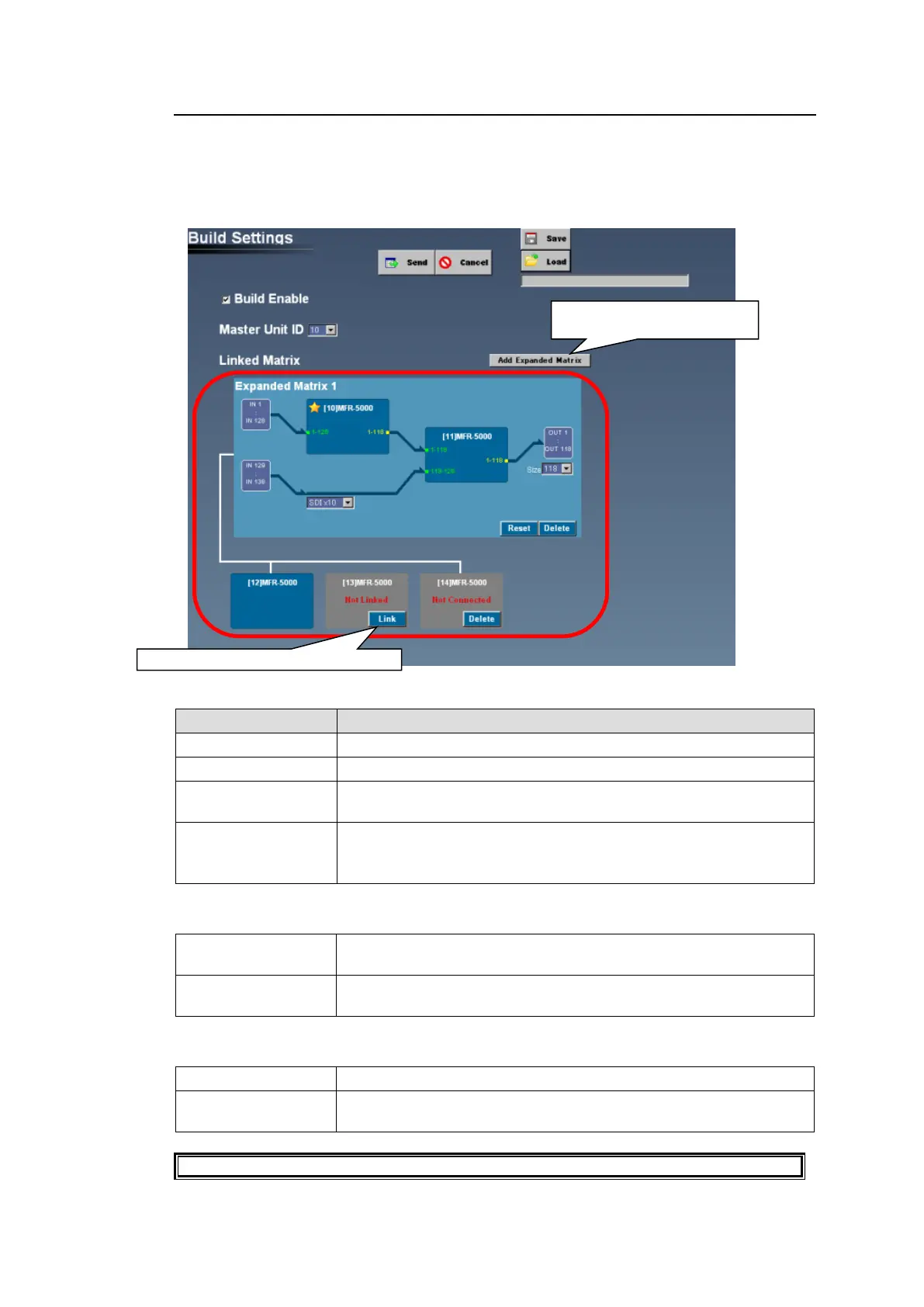
The Build Settings page allows you to set up Main Unit links. (Not supported by MFR-1000.)
The Main Unit Link feature provides two link types: Parallel Link and Expanded Matrix.
The figure below shows an Expanded Matrix setup.
* Note that MFR-80000/1616A units support only Parallel Link mode.
Enables the Main Unit Link feature.
Selects the Main Unit to be set as Master using the ID number.
When configuring an Expanded Matrix link, click this button to
display the Linked Matrix area.
Performs detailed Main Unit link settings.
Sets up signal connections inside the light blue background area.
(Expanded Matrix 1 block in the above example).
Linked Matrix (Outside the light blue background area.)
Clicking the Link button adds the unit to the Linkage and sets it as a
slave.
Clicking the button deselects the Linked (but unconnected) unit from
the Link system.
Linked Matrix (Inside light blue background area.)
Deselects all Main Units.
Resets the matrix setup (all signal connections) built in the Linked
Matrix area.
See Sec. 11 "Main Unit Link" for details on setting up Main Unit links.
Clicking this button shows the
Expanded Matrix setting area.
Clicking Link sets the unit to Slave.

 Loading...