24
Digital outputs: 0–3
Switching capacity when supplied by the Fronius Datamanager 2.0 plug-in
card: 3.2 W, 10.8/12.8 V in total for all 4 digital outputs
10.8 V:
Fronius IG, Fronius IG Plus, Fronius IG Plus V, Fronius IG Plus A,
Fronius CL, Fronius CL USA, Fronius IG 300–500
12.8 V:
Fronius Galvo, Fronius Symo
Switching capacity when supplied by an external power supply with min. 12.8–
max. 24 V DC (+ 20%), connected to Uint/Uext and GND: 1 A, 12.8–24 V DC
(depending on the external power supply) per digital output
The connection to the I/Os is made via the supplied mating connector.
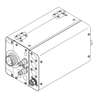
(8) Antenna plug
For screwing on the WLAN antenna or WLAN antenna extension cable, de-
pending on the inverter
(9) Modbus termination switch (for Modbus RTU)
Internal bus termination with 120-ohm resistance (yes/no)
Switch in position "on": Termination resistance of 120 ohm active
Switch in position "off": No termination resistance active
IMPORTANT! The termination resistance must be active for the first and last
device in an RS-485 bus.
(10) Fronius Solar Net master/slave switch
For switching between master and slave mode within a Fronius Solar Net ring
IMPORTANT! All LEDs on the Fronius Datamanager 2.0 plug-in card are off in
slave mode.
(11) Fronius Solar Net IN connection socket
Fronius Solar Net input colored red for connecting to other DATCOM compo-
nents (e.g., inverters, sensor cards)
For Fronius Datamanager 2.0 with Fronius Com Card function only!
(for Fronius IG, Fronius IG Plus, Fronius IG Plus V, Fronius IG Plus A, Fronius
CL, Fronius CL USA, Fronius IG 300–500 inverters)
No. Function