23
EN-US
(5) Connection LED
- Lights up green: There is an active connection within Fronius Solar Net
- Lights up red: There is an interrupted connection within Fronius Solar Net
- Does not light up: Fronius Datamanager 2.0 is in slave mode
(6) LAN connection socket
Ethernet interface colored blue for connecting the Ethernet cable
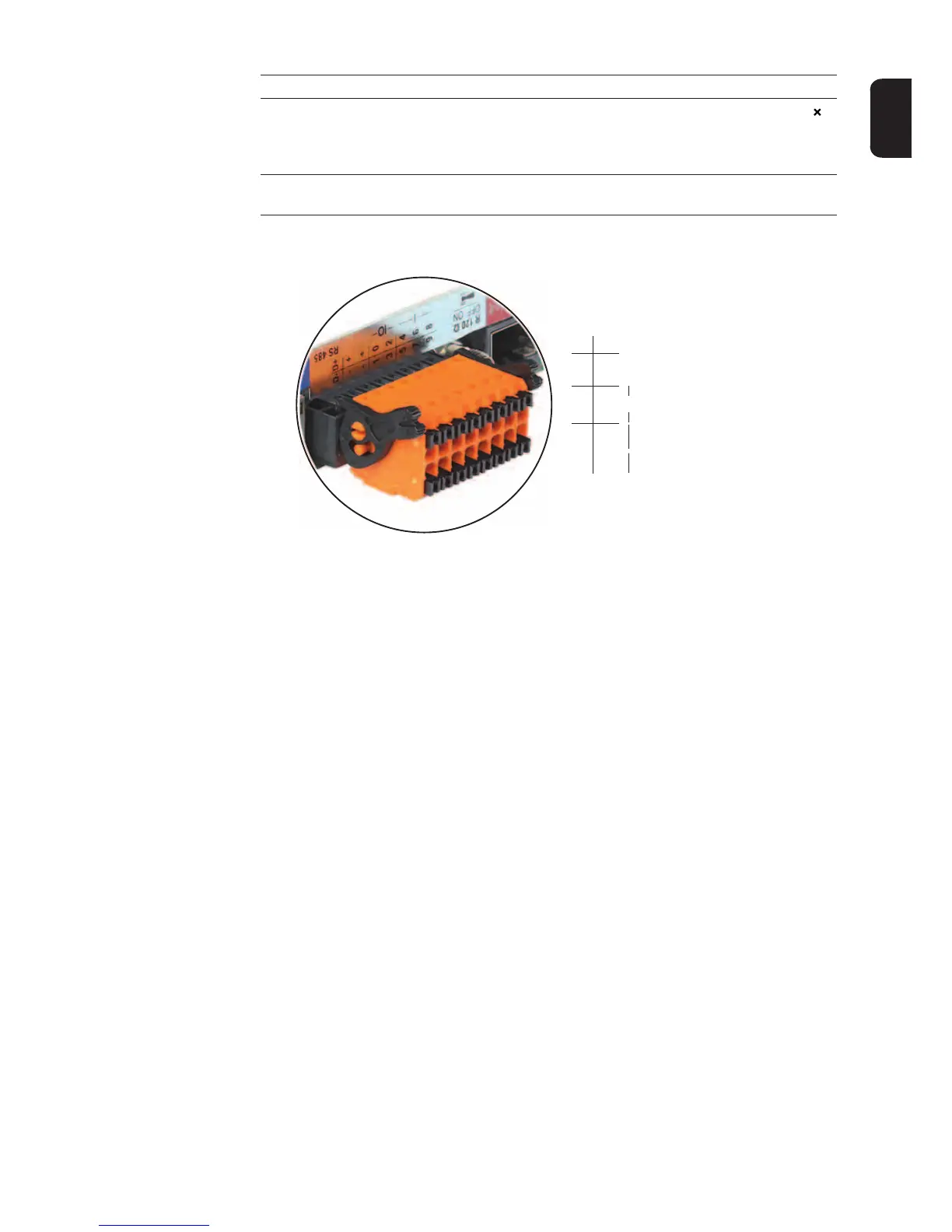
(7) I/Os
Digital inputs and outputs
Modbus RTU 2-wire (RS-485):
D- Modbus data -
D+ Modbus data +
Int./ext. power supply
- GND
+U
int
/U
ext
Output for internal voltage 10.8 V/12.8 V
or
Input for an external supply voltage
>12.8–24 V DC (+ 20%)
10.8 V:
Fronius IG, Fronius IG Plus, Fronius IG Plus V,
Fronius IG Plus A, Fronius CL, Fronius CL USA,
Fronius IG 300–500
12.8 V:
Fronius Galvo, Fronius Symo
Digital inputs: 0–3, 4–9
Voltage level: low = min. 0 V–max. 1.8 V; high = min. 3 V–max. 24 V DC (+
20%)
Input currents: dependent on input voltage; input resistance = 46 kOhm
No. Function
D-
-
-
1
3
5
7
9
D+
+
+
0
2
4
6
8
I IO RS485