8-14
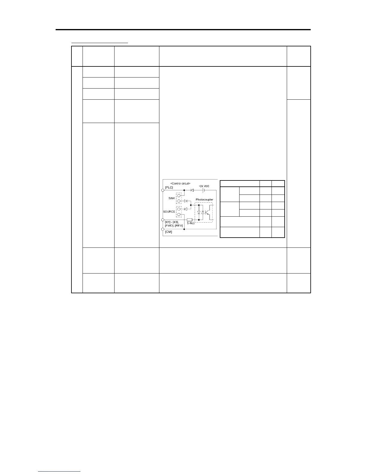
Item Min. Max.
ON level 0V 2V
Operation
voltage
(SINK)
OFF level 22V 27V
ON level 22V 27V
Operation
voltage
(SOURCE)
OFF level 0V 2V
Operation current at ON
(Input voltage at 0 V)
2.5mA 5mA
Allowable leakage
current at OFF
- 0.5mA
Digital input terminals
Classifi-
cation
Symbol Name Functions
Related
function
codes
[X1] Digital input 1
[X2] Digital input 2
[X3] Digital input 3
E01 to
E03
[FWD]
Forward
operation
command
[REV]
Reverse operation
command
Possible to assign various signals to terminals [X1] to
[X3], [FWD] and [REV] using function codes. For
details, refer to Section 9.2.2 "E codes."
By factory default, FWD and REV signals are
assigned to terminals [FWD] and [REV], respectively.
Common features
• Sink/Source switching feature:
Sink and source can be switched by using the
built-in jumper switch.
• Normal/negative logic input switching feature:
Switches the logic value (1/0) for ON/OFF of
terminals between [X1] to [X3], [FWD] or [REV],
and [CM]. If the logic value for ON between [X1]
and [CM] is 1 in the normal logic system, for
example, OFF is 1 in the negative logic system.
Digital input circuit specifications
E98,
E99
[PLC]
PLC signal
power
Connects to PLC output signal power supply.
(Rated voltage: +24 VDC, Maximum output current:
50 mA)
Digital input
[CM] Digital common
Common for digital input signals
(Isolated from terminals [11] and [Y1E].)

 Loading...


